
Automatic plant sampling device and using method thereof

An automatic sampling device, plant technology, applied in sampling devices, sampling, measuring devices, etc., can solve the problems of plant tissue contacting external air, freely adjusting slice thickness, unfavorable detection work, etc., to improve sampling efficiency, reduce pollution, Cleverly designed effects

Inactive Publication Date: 2021-12-21
济南泽逸生物科技有限公司
View PDF0 Cites 0 Cited by
  • Summary
  • Abstract
  • Description
  • Claims
  • Application Information

AI Technical Summary

Problems solved by technology

[0004] However, the existing sample preparation device has poor sealing performance, and cannot freely adjust the thickness of the slice according to the length of the required plant, and if the plant tissue cannot be stored in time, it is easy to make the plant tissue contact with the external air, thereby It is not conducive to the subsequent detection work, so a device that can seal slices and automatically make slices is needed

Method used


Image

  • Automatic plant sampling device and using method thereof
  • Automatic plant sampling device and using method thereof
  • Automatic plant sampling device and using method thereof

Examples


Embodiment 1

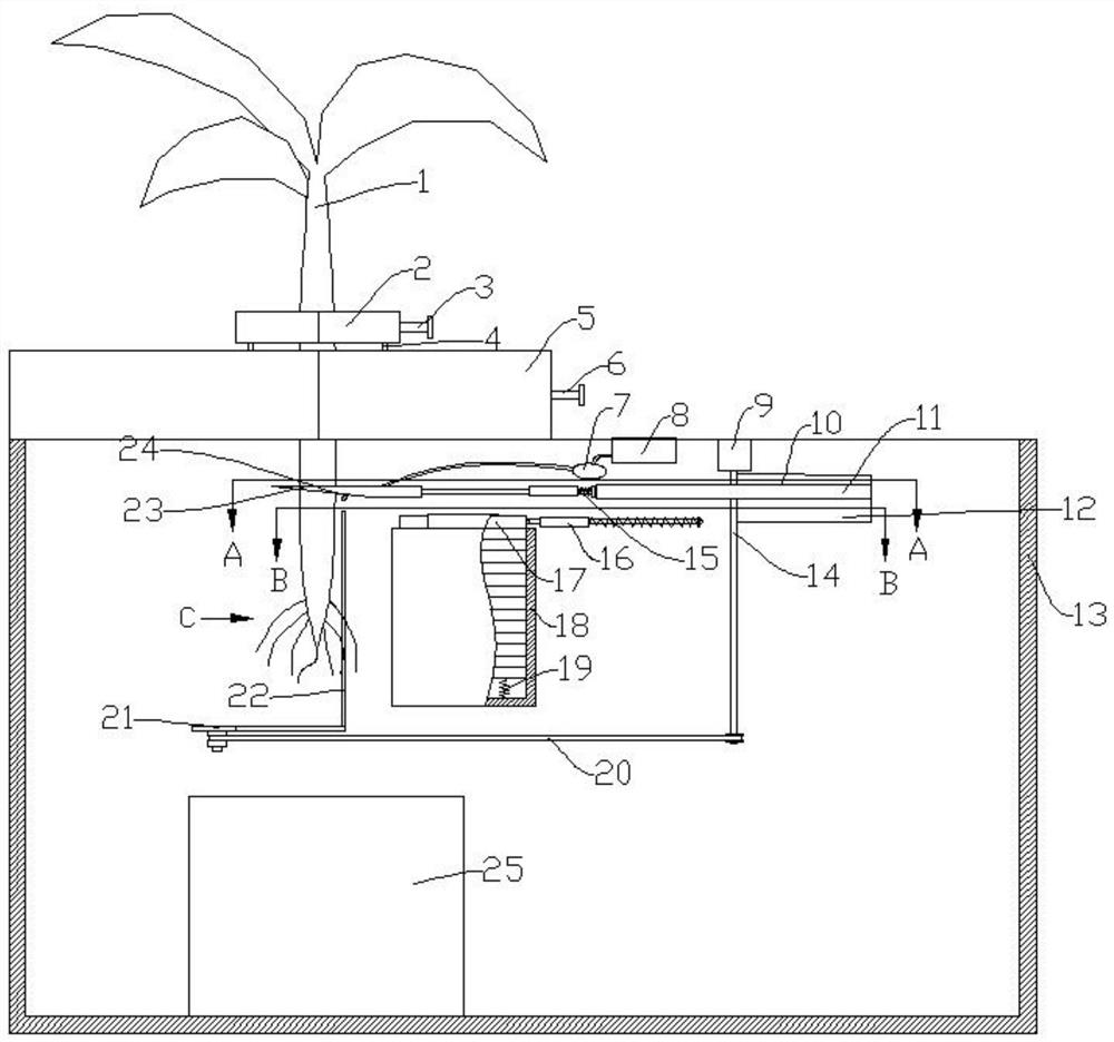
[0036] Reference attached Figure 1-6 , the present embodiment proposes a device for collecting plant tissue slices, including a sampling box 13, the sampling box 13 is fixedly connected with a lower jaw 5, the lower jaw 5 is slidably connected with a lower clamping plate, and the lower clamping plate is rotatably connected with a lower clamping plate. Jaw bar 6, the lower jaw bar 6 is threadedly connected with the lower jaw 5.

[0037] Therefore, when the lower jaw rod 6 rotates, it can drive the lower clamping plate to move in a direction close to the plant 1 without causing the lower clamping plate to rotate, thereby facilitating the mutual cooperation of the lower clamping plate and the lower jaw 5 to realize plant growth. 1 clamping work.

[0038]An upper jaw 2 is also arranged above the lower jaw 5, and the upper jaw 2 is slidably connected with an upper clamping plate 201, and the upper clamping plate 201 is rotatably connected with an upper jaw rod 3, and the upper ja...

Embodiment 2

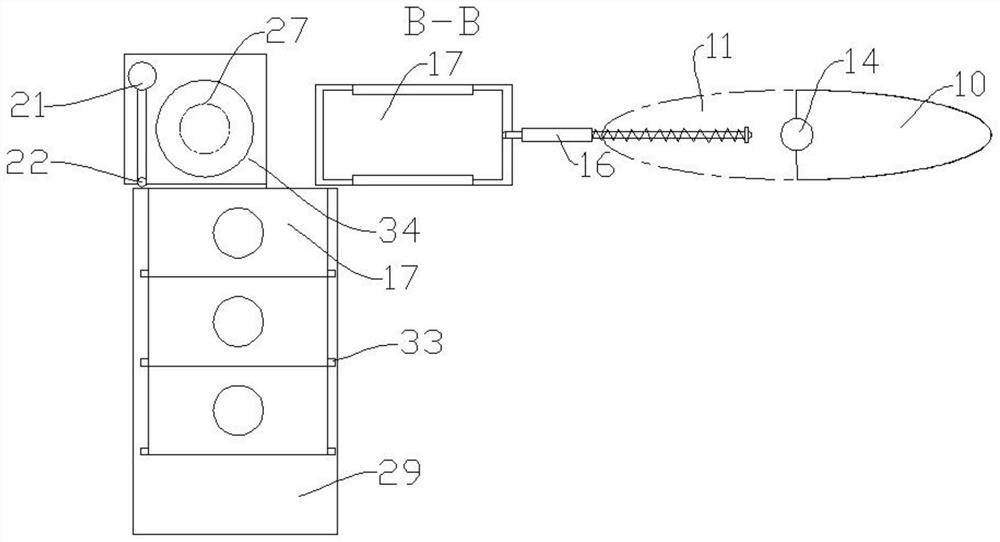
[0066] like Figure 1-6 As shown, the other structures are the same as in Embodiment 1, the difference is that in this embodiment, the sampling box 13 is fixedly connected with a cover glass box arranged above the conveyor belt 29, and several covers are arranged in the cover glass box. Glass slide 30, one side of the cover glass box is provided with an opening for the cover glass 30 to pass through; the bottom end of the cover glass box is slidably connected with a cover glass dial 31 adapted to the cover glass push rod 33, and the cover glass The dial 31 is connected to the inner wall of the cover glass box through the cover glass spring 32 , and the cover glass dial 31 is arranged on one side of the cover glass 30 . The other side of the conveyor belt 29 is provided with a collection box 35 . ,

[0067] In the initial state, the cover glass spring 32 is in a free stretch state, so the cover glass spring 32 will not drive the cover glass dial 31 to move. When the cover gla...


PUM


Abstract

The invention discloses an automatic plant sampling device and a using method thereof. The automatic plant sampling device comprises a sampling box, wherein the sampling box is fixedly connected with a lower clamping jaw, the lower clamping jaw is slidably connected with a lower clamping plate, the lower clamping plate is rotatably connected with a lower clamping jaw rod, and the lower clamping jaw rod is in threaded connection with the lower clamping jaw; an upper clamping jaw is further arranged above the lower clamping jaw, the upper clamping jaw is in sliding connection with an upper clamping plate, the upper clamping plate is rotationally connected with an upper clamping jaw rod, and the upper clamping jaw rod is in threaded connection with the upper clamping jaw; a bottom end of the upper clamping jaw is connected with a slicing telescopic rod, the lower clamping jaw is provided with a through hole for the slicing telescopic rod to penetrate through, and spaces for plants to pass through are reserved between the upper clamping jaw and the upper clamping plate and between the lower clamping jaw and the lower clamping plate; and a cutter is also slidably connected in the sampling box. The device is simple to operate, can automatically sample plants according to the length of the required plants, and can automatically make plant specimens.

Description

technical field [0001] The invention relates to the technical field of plant quarantine, in particular to an automatic plant sampling device and a method for using the same. Background technique [0002] Phytosanitary measures to prevent the spread of harmful organisms in the circulation of plants and their products by means of legislation. An aspect of plant protection characterized by the macroscopic prevention of the introduction, establishment and spread of all pests, especially those not found in the region. Because it is legally mandatory, "prevention by regulations" and "prevention by administrative measures" are often used as synonyms in international literature. [0003] Based on the above, in the process of plant quarantine, it is necessary to slice and sample plants, and then place these sliced ​​samples under a microscope to observe the changes in their internal tissues, and cooperate with other chemical experimental data of the sampled samples to confirm the fi...

Claims


Application Information

Patent Timeline
Patent Type & Authority Applications(China)
IPC IPC(8): G01N1/06G01N1/28
CPCG01N1/06G01N1/2806
Inventor 张祥胜
Owner 济南泽逸生物科技有限公司
Learn More