Covered stent
A covered stent and film-covered technology, which is applied in the field of medical devices, can solve problems such as adaptive bending and deformation, and achieve the effect of reducing the force on the wave coil and avoiding damage to the blood vessel wall
- Summary
- Abstract
- Description
- Claims
- Application Information
AI Technical Summary
Problems solved by technology
Method used
Image

Examples
Embodiment 1
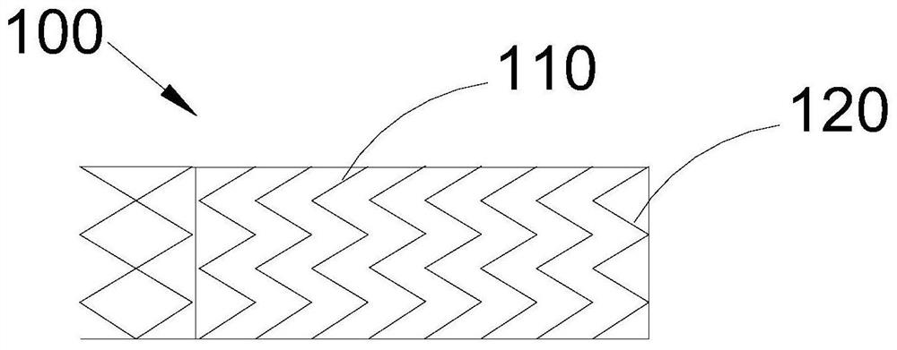
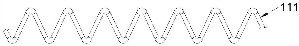
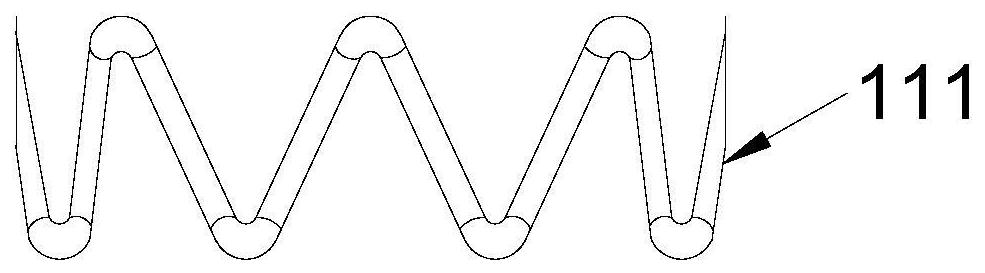
[0049] refer to Figure 1 to Figure 4, the covered stent 100 provided in Embodiment 1 of the present application includes a bare stent 110 and a covered film 120 . The bare stent 110 includes a support 112 and at least two corrugations 111 arranged at intervals along a first direction, and the covering film 120 covers the bare stent 110 along the circumferential direction of the bare stent 110 along the first direction. The support member 112 is disposed between two adjacent wave coils 111 and is respectively connected to two adjacent wave coils 111; the support member 112 is defined when the force received by the wave coil 111 connected to it in the first direction is less than a preset value. The distance in the first direction of the wave coil 111 connected thereto.
[0050] In this way, by setting the support 112 between the adjacent two wave coils 111, the support 112 connects the two adjacent wave coils 111, and when the external force received by the bare bracket 110 i...
Embodiment 2
[0059] refer to Figure 5 to Figure 7 Embodiment 2 of the present application provides a stent-graft 200 . The difference between the stent-graft 200 of the second embodiment and the stent-graft 100 of the first embodiment lies in that the structure of the support member 212 is different.
[0060] The support 212 includes a first support part 2121 and a second support part 2122, the elastic modulus of the first support part 2121 is greater than the elastic modulus of the second support part 2122; the second support part 2122 is arranged on the outer periphery of the first support part 2121 On the other hand, the structure of the second supporting part 2122 includes one of strip shape, cylinder shape and spiral shape.
[0061] refer to Figure 5 , the first support portion 2121 is a solid cylindrical structure, the second support portion 2122 is a hollow cylinder, and the second support portion 2122 wraps around the outer peripheral side of the first support portion 2121 .
...
Embodiment 3
[0069] refer to Figure 8 to Figure 9 Embodiment 3 of the present application provides a stent-graft 300 . The difference between the stent-graft 300 in Embodiment 3 and the stent-graft 100 in Embodiment 1 is that the structure of the support member 312 is different.
[0070] The support 312 includes a first support part 3121 and a second support part 3122, the elastic modulus of the first support part 3121 is greater than that of the second support part 3122; the second support part 3122 is arranged on the first support part 3121 at intervals , and the axial length of the first supporting portion 3121 is greater than the axial length of the second supporting portion 3122 .
[0071] The modulus of elasticity of the first supporting part 3121 is greater than that of the second supporting part 3122, and the first supporting part 3121 is made of stainless steel or nickel-titanium alloy. In practical application, the first supporting portion 3121 is rarely deformed after being ac...
PUM
 Abstract
Description
Claims
Application Information
 - R&D
- Intellectual Property
- Life Sciences
- Materials
- Tech Scout
- Unparalleled Data Quality
- Higher Quality Content
- 60% Fewer Hallucinations
Browse by: Latest US Patents, China's latest patents, Technical Efficacy Thesaurus, Application Domain, Technology Topic, Popular Technical Reports.
© 2025 PatSnap. All rights reserved.Legal|Privacy policy|Modern Slavery Act Transparency Statement|Sitemap|About US| Contact US: help@patsnap.com