
Ionic solution three-cycle coupling low-temperature heat supply system and using method

An ionic solution and heating system technology, applied in heating systems, hot water central heating systems, heating methods, etc., can solve problems such as failure to work normally, pollution, poor heat transfer performance, etc.

Pending Publication Date: 2021-12-24
TECHNICAL INST OF PHYSICS & CHEMISTRY - CHINESE ACAD OF SCI
View PDF0 Cites 0 Cited by
  • Summary
  • Abstract
  • Description
  • Claims
  • Application Information

AI Technical Summary

Problems solved by technology

[0005] However, when the existing air-source heat pump heating system operates in a sub-zero low-temperature and high-humidity environment, the equipment is prone to frost, poor heat transfer performance, and unable to work normally and continuously, and the ground source and water source heat pumps are severely restricted by the natural environment, such as geological conditions. , groundwater and surface water restrictions, etc. In addition, electric energy, fuel oil, coal-fired boilers, etc. have high energy consumption and serious pollution

Method used


Image

  • Ionic solution three-cycle coupling low-temperature heat supply system and using method
  • Ionic solution three-cycle coupling low-temperature heat supply system and using method
  • Ionic solution three-cycle coupling low-temperature heat supply system and using method

Examples


Embodiment Construction

[0037] In order to make the purpose, technical solutions and advantages of the present invention clearer, the technical solutions in the present invention will be clearly and completely described below in conjunction with the accompanying drawings in the present invention. Obviously, the described embodiments are part of the embodiments of the present invention , but not all examples. Based on the embodiments of the present invention, all other embodiments obtained by persons of ordinary skill in the art without creative efforts fall within the protection scope of the present invention.

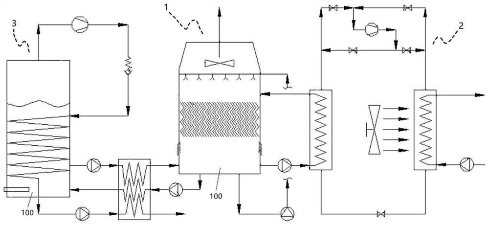
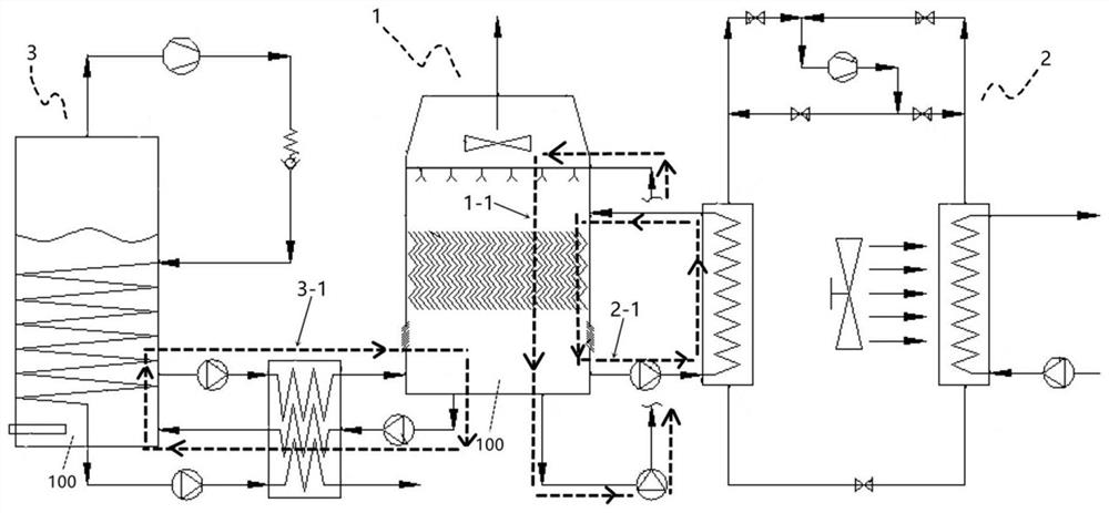
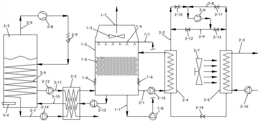
[0038] Combine below Figure 1 to Figure 3 Describe an ion solution three-cycle coupled low-temperature heating system of the present invention, including: a low-temperature heat collection subsystem 1, a heat pump energy supply subsystem 2, and an enthalpy-increasing regeneration subsystem 3. The low-temperature heat collection subsystem 1 is loaded with ions Solution 100, low-temperature h...


PUM


Abstract

The invention relates to an ionic solution three-cycle coupling low-temperature heat supply system and a using method. The ionic solution three-cycle coupling low-temperature heat supply system comprises a low-temperature heat collection subsystem, a heat pump energy supply subsystem and an enthalpy increasing regeneration subsystem. The low-temperature heat collection subsystem is provided with an ionic solution heat collection circulation loop, and the heat pump energy supply subsystem is provided with an ionic solution energy supply circulation loop. And the enthalpy increasing regeneration subsystem is provided with an ionic solution regeneration circulation loop. The low-temperature heat collection subsystem and the enthalpy increasing regeneration subsystem are communicated with each other through the ionic solution regeneration circulation loop, and the enthalpy increasing regeneration subsystem supplies and conveys a regenerated ionic solution to the low-temperature heat collection subsystem through the ionic solution regeneration circulation loop. The low-temperature heat collection subsystem and the heat pump energy supply subsystem are communicated with each other through the ionic solution energy supply circulation loop, and the low-temperature heat collection subsystem transfers heat to the heat pump energy supply subsystem through the ionic solution energy supply circulation loop. According to the ionic solution three-cycle coupling low-temperature heat supply system and the using method, a small amount of electric energy is input through a heat pump unit, and thus low-temperature heat energy below the freezing point can be transferred to the high-temperature position. And the requirements of building heating and heat supply are met.

Description

technical field [0001] The invention relates to the technical field of heating equipment, in particular to an ion solution three-circulation coupled low-temperature heating system and a use method. Background technique [0002] With the rapid development of my country's economy and irregular climate changes, the demand for heating and heating in the "low temperature and high humidity" areas in the south will gradually increase. Due to the unscientific traditional heating methods, low energy efficiency of equipment, and unreasonable use of energy, it has been criticized. Great waste, low temperature heating technology came into being. [0003] In view of the climate characteristics of low temperature and high humidity in southern my country in winter, the air contains a large amount of low-level heat energy converted from solar energy. Due to the high wet bulb temperature, the low-grade energy storage in the air is huge, but the low-level heat energy below freezing point is po...

Claims


Application Information

Patent Timeline
IPC IPC(8): F24D3/02F24D3/18F24D19/10F25B30/06
CPCF24D3/02F24D3/18F24D19/1039F25B30/06Y02B30/12
Inventor 张化福张振涛杨俊玲张钰越云凯于泽王有栋
Owner TECHNICAL INST OF PHYSICS & CHEMISTRY - CHINESE ACAD OF SCI
Learn More