Full-automatic silicon wafer surface efficient scrubbing and cleaning device and operation method

A technology for cleaning the surface of silicon wafers, which is applied to cleaning methods and utensils, cleaning methods using liquid, heating devices, etc. Probability, the effect of speeding up the cooling rate and improving the efficiency

Active Publication Date: 2021-12-31
浙江丽水中欣晶圆半导体科技有限公司 +1
View PDF8 Cites 3 Cited by
  • Summary
  • Abstract
  • Description
  • Claims
  • Application Information

AI Technical Summary

Problems solved by technology

[0002] After the silicon wafer is cut, it needs to be degummed and cleaned; the silicon wafer is dried by hot air after being cleaned in the washing machine; at present, the temperature of the silicon wafer dried by the silicon wafer washing machine is 60-70 degrees Celsius. Affect the detection accuracy of the sorter for silicon wafers
[0003] The traditional solution is to place the silicon wafers for a period of time until the temperature of the

Method used


Image

  • Full-automatic silicon wafer surface efficient scrubbing and cleaning device and operation method
  • Full-automatic silicon wafer surface efficient scrubbing and cleaning device and operation method
  • Full-automatic silicon wafer surface efficient scrubbing and cleaning device and operation method

Examples


Embodiment 1

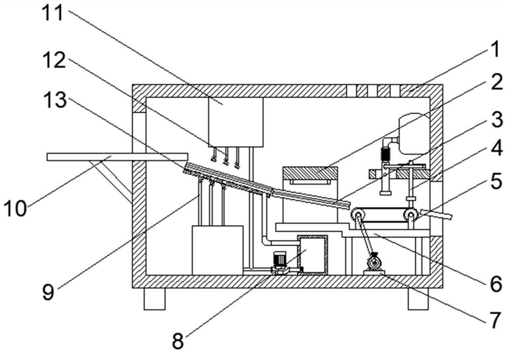
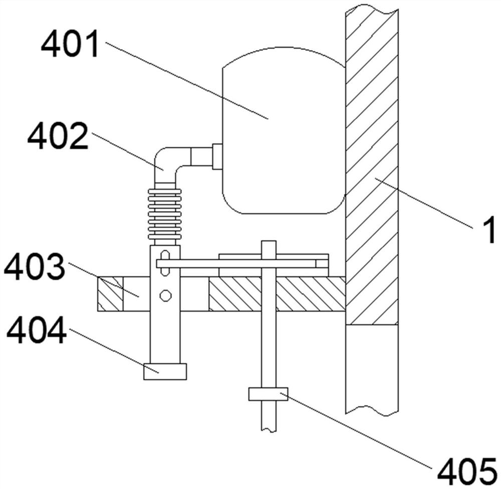
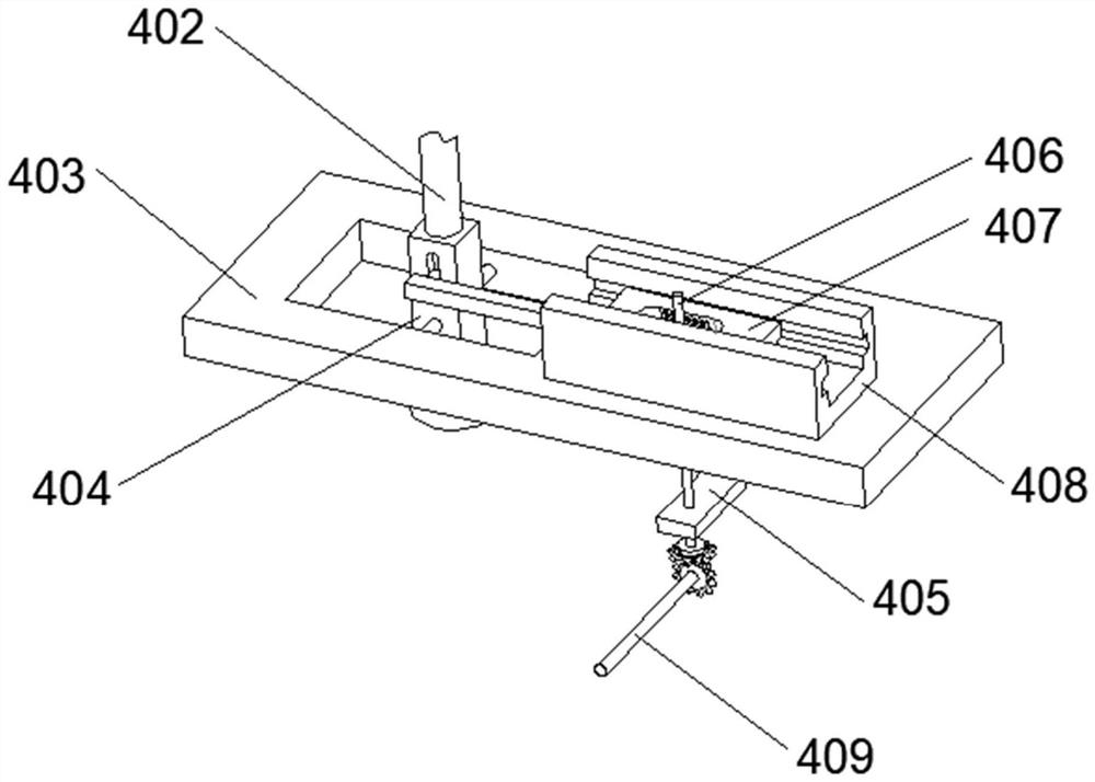
[0034] see figure 2 , image 3 with Figure 4As shown, the above-mentioned cooling mechanism 4 includes a refrigeration compressor 401 and a support plate 403 fixedly connected to the inner wall of the housing 1, a rotating hole is opened on the top surface of the support plate 403, and a hose 402 is connected to the output end of the refrigeration compressor 401. The bottom end of the pipe 402 is fixedly equipped with a nozzle 404, the top side of the nozzle 404 is provided with a first chute, the bottom of the nozzle 404 moves through the rotating hole, and the middle part of the nozzle 404 is connected to the inner wall of the rotating hole through a fixed pin. The fixing pin plays a position-limiting effect on the nozzle 404, which facilitates the rotation of the nozzle 404, so that the nozzle 404 can quickly and evenly cool down the dried silicon wafer. The top of the support plate 403 is fixedly equipped with a mounting block 408, and The top surface is provided with ...

Embodiment 2

[0037] see Figure 5 As shown, the above-mentioned recovery mechanism 8 includes a recovery box 805 fixedly connected to the inner wall of the housing 1. The top of the recovery box 805 is connected with a water inlet pipe 801, and the bottom of the recovery box 805 is connected with a drain pipe 803. The two output ends of the drain pipe 803 They communicate with the two water storage tanks 11 respectively, a water pump 802 is arranged in the middle of the drain pipe 803, and a filter screen 804 is provided at the junction of the drain pipe 803 and the recovery box 805, and dust and debris are filtered out through the filter screen 804, and then The filtered water is discharged through the water pump 802 for recycling.

[0038] see Image 6 As shown, the above-mentioned support mechanism 13 includes a slant plate 1301 fixedly connected to the inner wall of the housing 1, the top surface of the slant plate 1301 is provided with a third chute, and the inner walls on both sides...


PUM


Abstract

The invention relates to a full-automatic silicon wafer surface efficient brushing and cleaning device and an operation method. The full-automatic silicon wafer surface efficient brushing and cleaning device comprises a shell, a cavity is formed in the shell, a supporting mechanism used for containing a silicon wafer for cleaning is arranged in the middle of the cavity, water storage tanks are fixedly mounted on the upper side and the lower side of the supporting mechanism, a guide plate is arranged on one side of the supporting mechanism, a recycling mechanism is arranged below the guide plate, and a cooling mechanism used for cooling the silicon wafer is arranged at the position, on one side of the recycling mechanism, on the inner wall of the shell. An incomplete gear is driven to rotate through running of a second rotating shaft, so that a moving plate slides in a reciprocating limiting manner in a second sliding groove, a spray head rotates under the action of a fixing pin, cold air is uniformly sprayed to the dried silicon wafer through swinging of the air spraying end of the spray head, and therefore the cooling speed of the silicon wafer is increased, and meanwhile cold air is uniformly sprayed, so that the probability of damage caused by uneven heating of the silicon wafer is reduced.

Description

technical field [0001] The invention relates to the technical field of silicon wafer cleaning, in particular to a fully automatic silicon wafer surface high-efficiency brush cleaning device and an operation method. Background technique [0002] After the silicon wafer is cut, it needs to be degummed and cleaned; the silicon wafer is dried by hot air after being cleaned in the washing machine; at present, the temperature of the silicon wafer dried by the silicon wafer washing machine is 60-70 degrees Celsius. Affect the detection accuracy of the sorter for silicon wafers. [0003] The traditional solution is to place the silicon wafers for a period of time until the temperature of the silicon wafers drops to about 30 degrees Celsius, and then go to the sorting machine for sorting; this will prolong the processing time and affect the production efficiency. Blowing cold air on the wafer cannot effectively cool down the silicon wafer. At the same time, the traditional silicon w...

Claims


Application Information

Patent Timeline
IPC IPC(8): B08B3/02B08B3/14F26B23/06H01L21/67H01L21/02
CPCB08B3/022B08B3/14F26B23/06H01L21/67051H01L21/67109H01L21/02076
Inventor 戚定定
Owner 浙江丽水中欣晶圆半导体科技有限公司
Why Eureka
Try Eureka