Magnetic saturation iron core direct current fault current limiter capable of performing secondary active current limiting and current limiting method
A technology of DC fault and current limiter, which is applied to emergency protection circuit devices, variable inductors, variable transformers, etc. for limiting overcurrent/overvoltage, and can solve superimposed damage and slow energy absorption speed of DC systems , limited current limiting effect and other issues, to achieve superior and significant current limiting effect, improve secondary current limiting ability, and increase absorption speed
- Summary
- Abstract
- Description
- Claims
- Application Information
AI Technical Summary
Problems solved by technology
Method used
Image


Examples
Embodiment Construction
[0035] The following will clearly and completely describe the technical solutions in the embodiments of the present invention in combination with the embodiments of the present invention. Obviously, the described embodiments are only some of the embodiments of the present invention, not all of them. Based on the embodiments of the present invention, all other embodiments obtained by persons of ordinary skill in the art without creative efforts fall within the protection scope of the present invention.
[0036] It should be noted that, in the case of no conflict, the embodiments of the present invention and the features in the embodiments can be combined with each other.
[0037] The present invention will be further described below in conjunction with specific examples, but not as a limitation of the present invention.
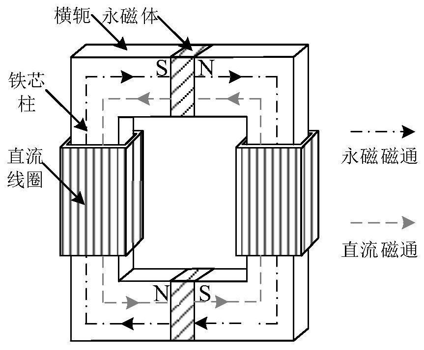
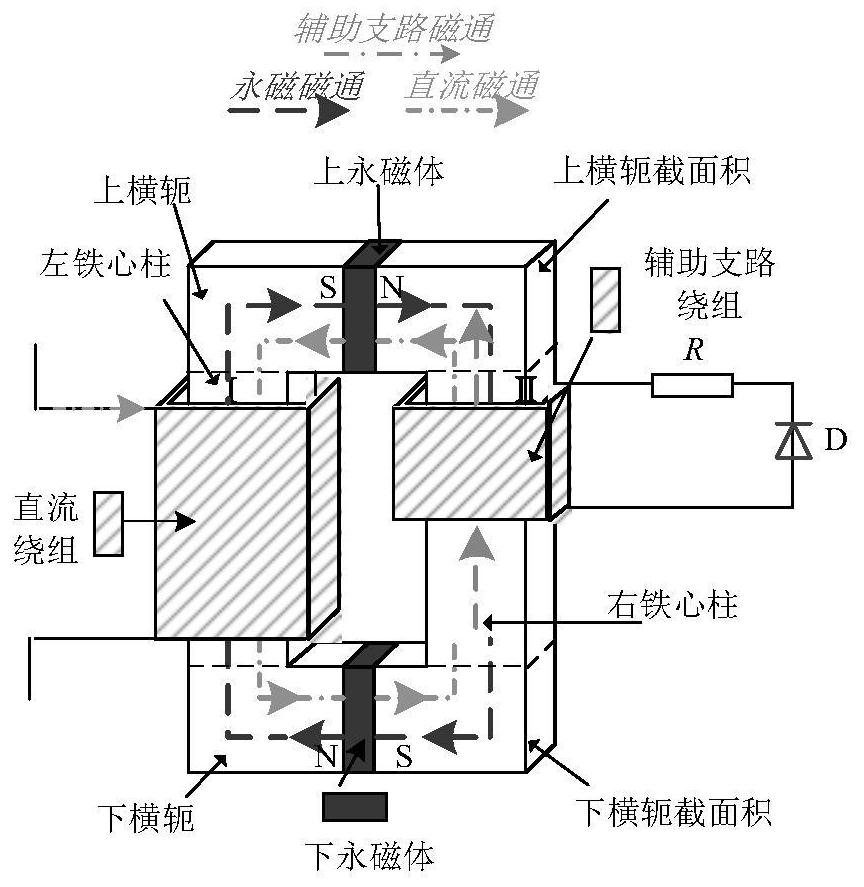
[0038] In this embodiment, a magnetic coupling branch is added outside the main branch windings of the left and right core columns of the traditional magnetic...
PUM
 Abstract
Description
Claims
Application Information
PatSnap Eureka turns technology decisions into work you can execute. Powered by our Innovation Knowledge Graph, it runs expert workflows across engineering, life sciences, materials and intellectual property. Get your review-ready output in minutes.


