Substrate scribing and carrying device

A handling device and scribing technology, applied in the directions of transportation and packaging, cleaning methods and utensils, laser welding equipment, etc., can solve the problems of broken ceramic substrates, easy scratches, etc., to avoid messy accumulation, facilitate rapid handling, and facilitate Effects of slag removal and positioning handling

Active Publication Date: 2022-01-04
张家港力勤机械有限公司
View PDF9 Cites 2 Cited by
  • Summary
  • Abstract
  • Description
  • Claims
  • Application Information

AI Technical Summary

Problems solved by technology

[0003] In order to overcome that the ceramic substrate after laser cutting will fall into the empty cabin under the laser cutting platform, the operator will only Remove the ceramic substrate from the empty cabin of the cutting platform. At the same time, when the ceramic substrate falls into the empty cabin, it is easy to scratch and break the ceramic substrate. The invention provides a substrate scribing and handling device

Method used


Image

  • Substrate scribing and carrying device
  • Substrate scribing and carrying device
  • Substrate scribing and carrying device

Examples


Embodiment 1

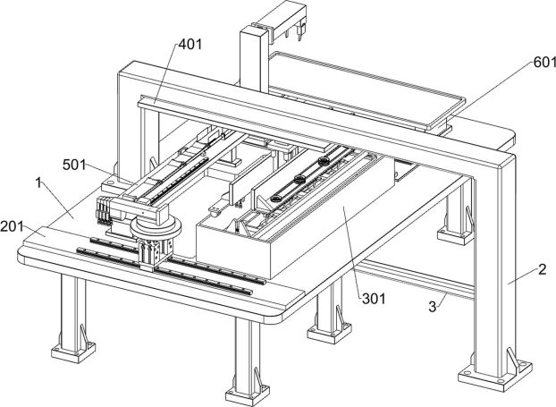
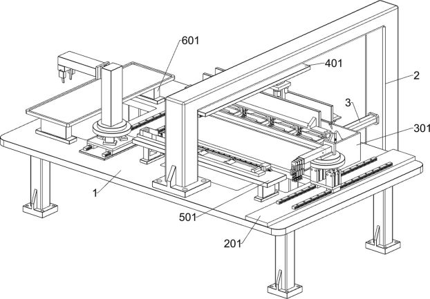
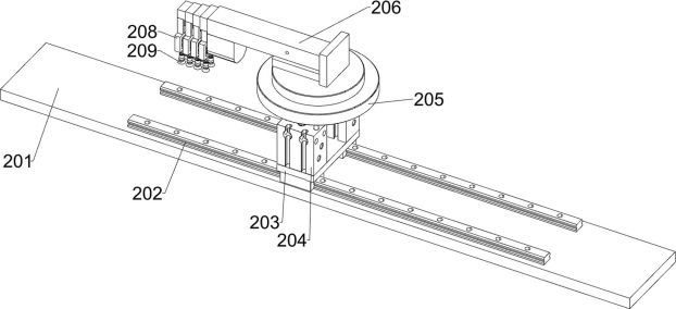
[0036] A substrate scribing and conveying device, such as Figure 1-6 As shown, it includes a frame 1, a gantry 2, a connecting rod 3, a handling system and a clamping system; the left part of the upper side of the frame 1 is bolted to the gantry 2; the right part of the frame 1 is connected to the connecting rod 3 by bolts; The right side of the connecting rod 3 is fixedly connected with the gantry frame 2; the upper front part of the frame 1 is connected with a handling system; the upper right part of the frame 1 is connected with a clamping system.

[0037] When in use, first place the substrate scribing and conveying device at the required position, place the rack 1 on a stable position, first move the conveying system to the right rear side where the laser is ready to cut the oval ceramic substrate, and wait for the laser to cut the ceramic When the substrate is cut in half, the handling system moves to the cut ceramic substrate and holds the ceramic substrate. After the ...

Embodiment 2

[0043] On the basis of Example 1, such as figure 1 with Figure 7-16 As shown, it also includes a slag removal and handling system. The lower side of the gantry 2 is connected with a slag removal and handling system. The slag removal and handling system includes a third mounting plate 401, a second electric slide rail 402, and a second fixing plate 403. , the second electric push rod 404, the first fixed block 405, the fourth mounting plate 406, the fifth mounting plate 407, the slag removal component and the handling component; the gantry frame 2 lower side bolts are connected with the third mounting plate 401; the third A second electric slide rail 402 is connected with each bolt at the lower front part and the lower rear part of the mounting plate 401; the two second electric slide rails 402 are connected with a second fixed plate 403 by slider bolts; the second fixed plate 403 Each of the four corners of the lower side is fixedly connected with a second electric push rod ...

Embodiment 3

[0055] On the basis of Example 2, such as figure 1 with Figure 17-18 As shown, it also includes a stacking system, the upper rear of the frame 1 is connected to the stacking system, and the stacking system also includes a first square base 601, a third placement plate 602, a sixth mounting plate 603, a fourth Electric slide rail 604, fourth fixed plate 605, second square base 606, second electric turntable 607, vertical plate 608, fifth electric slide rail 609, fifth fixed plate 610, horizontal plate 611 and manipulator 612; Rack 1 Two first square bases 601 are fixedly connected to the upper rear part; the third placing board 602 is fixedly connected to the upper side of the two first square bases 601; the sixth mounting board is fixedly connected to the upper rear part of the frame 1 603, the sixth mounting plate 603 is located in front of the first square base 601; each bolt on the upper front and upper rear of the sixth mounting plate 603 is connected with a fourth elect...


PUM


Abstract

The invention relates to the field of laser cutting, in particular to a substrate scribing and carrying device. The technical problems are as follows: all ceramic substrates after laser cutting fall into a void cabin below a laser cutting platform, an operator can take out the ceramic substrates from the void cabin of the cutting platform only when laser cutting is completed or stopped, and meanwhile, the ceramic substrates are easily scratched and broken when falling into the void cabin. According to the technical scheme, the substrate scribing and carrying device comprises a rack, a carrying system, a clamping system and the like; the carrying system is connected to the front portion of the upper side of the rack; and the clamping system is connected to the right portion of the upper side of the rack. According to the substrate scribing and carrying device, conveying of the oval ceramic substrates after laser cutting is achieved, manual collection of the ceramic substrates falling into the void cabin after laser cutting is replaced, and the situation that the product quality is affected due to the fact that the ceramic substrates fall off and are scratched is prevented.

Description

technical field [0001] The invention relates to the field of laser cutting, in particular to a substrate scribing and conveying device. Background technique [0002] In the prior art, the ceramic substrate after laser cutting is dropped into the empty cabin under the laser cutting platform. Only when the laser cutting is completed or stopped, the operator will go to the empty cabin of the cutting platform to take out the ceramic substrate. When the substrate falls into the empty cabin, it is easy to scratch the ceramic substrate and affect the quality of the ceramic substrate. When the laser cuts the ceramic substrate, when the laser beam with high power density is irradiated on the surface of the ceramic substrate, the part to be cut on the surface of the ceramic substrate is in the Melting or vaporization occurs in a very short period of time, and slag is formed on the cutting edge and both sides. If the slag is not removed, the slag will solidify again, and it will firmly...

Claims


Application Information

Patent Timeline
Patent Type & Authority Applications(China)
IPC IPC(8): B65G47/91B65G61/00B08B5/02B23K26/38B23K26/70
CPCB65G47/912B65G61/00B08B5/02B23K26/38B23K26/70Y02P40/57
Inventor 王汉力郭晓斌蒋波
Owner 张家港力勤机械有限公司
Why Eureka
Try Eureka