
Direct-current solid-state transformer for medium-voltage direct-current system and control method of direct-current solid-state transformer

A solid-state transformer, DC system technology, applied in the direction of converting DC power input to DC power output, transformer/inductor core, transformer/inductor components, etc., can solve the problem of increasing the cost of DC transformers and increasing the complexity of control systems and other problems, to achieve the effect of reducing the volume, optimizing the current situation and soft switching characteristics, and reducing the number of

Pending Publication Date: 2022-01-04
HEBEI UNIV OF TECH
View PDF0 Cites 0 Cited by
  • Summary
  • Abstract
  • Description
  • Claims
  • Application Information

AI Technical Summary

Problems solved by technology

For ISOP converters, considering the needs of bidirectional power transmission, dual active bridge (DAB) converters are often used as sub-modules, but limited by the withstand voltage level of semiconductor switches, the input and output voltages of sub-modules are also limited, so A large number of sub-modules are required to meet the voltage level, which means that a large number of semiconductor switches, intermediate frequency transformers and gate drive components are required, which not only increases the cost of the DC transformer, but also increases the complexity of the control system

Method used


Image

  • Direct-current solid-state transformer for medium-voltage direct-current system and control method of direct-current solid-state transformer
  • Direct-current solid-state transformer for medium-voltage direct-current system and control method of direct-current solid-state transformer
  • Direct-current solid-state transformer for medium-voltage direct-current system and control method of direct-current solid-state transformer

Examples


Embodiment Construction

[0019] The technical solutions of the present invention will be specifically described below in conjunction with the accompanying drawings. Apparently, the described embodiments are only some but not all embodiments of the present invention. Based on the embodiments of the present invention, all other embodiments obtained by persons of ordinary skill in the art without making creative efforts belong to the protection scope of the present invention.

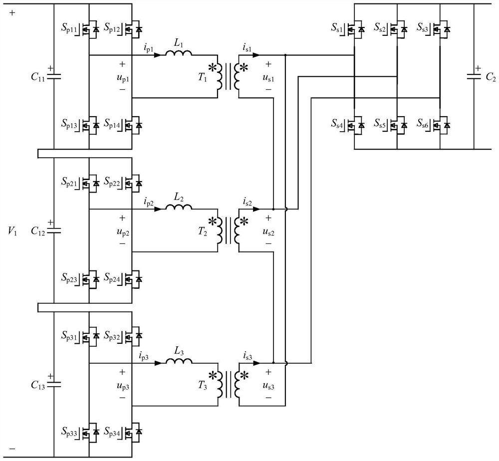
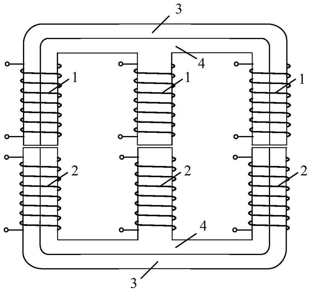
[0020]The present invention provides a DC solid-state transformer for a medium-voltage DC system. The topology of the DC solid-state transformer includes three H-bridge modules, three intermediate-frequency inductors, an intermediate-frequency transformer module, and a three-phase bridge module; wherein, each An H-bridge module is composed of a DC capacitor and two bridge arms connected in parallel. Each bridge arm is composed of two upper and lower semiconductor switches in series. Three H-bridge modules are connected in series t...


PUM


Abstract

The invention relates to a direct-current solid-state transformer for a medium-voltage direct-current system and a control method of the direct-current solid-state transformer. A topological structure comprises three H-bridge modules, three intermediate-frequency inductors, an intermediate-frequency transformer module and a three-phase bridge module; each H-bridge module is formed by connecting a direct-current capacitor and two bridge arms in parallel, each bridge arm is formed by connecting two semiconductor switches in series, and the three H-bridge modules are connected in series to form a primary side circuit; the three-phase bridge module is formed by connecting a direct-current capacitor and three bridge arms in parallel, and the three-phase bridge module forms a secondary side circuit; the primary side of the intermediate-frequency transformer module is connected with the midpoint of the bridge arm of each H-bridge module through the intermediate-frequency inductor, and the secondary side of the intermediate-frequency transformer module is connected with the midpoints of the three bridge arms of the three-phase bridge module. On the premise that the voltage stress of the semiconductor switches is not improved, the voltage of the primary side circuit is improved to three times that of a traditional DAB converter; and the three H-bridge modules connected in series effectively reduce the ripple content, so that the size of a filter is reduced.

Description

technical field [0001] The invention belongs to the technical field of power electronics, in particular to a DC solid-state transformer used in a medium-voltage DC system and a control method thereof. Background technique [0002] With the increasing popularity of new energy and energy storage components, the emergence of DC loads, frequency conversion equipment, and the increasing demand for diverse power consumption, the traditional AC power distribution method is facing unprecedented challenges. Compared with the traditional AC distribution network, the DC distribution network has economic and technical advantages in many fields, and has great development prospects. In the DC distribution network, the DC transformer is the key component to realize the interconnection of the DC buses of different voltage levels. At present, due to the limitation of the withstand voltage level of semiconductor switches, DC transformers mostly adopt two topologies of modular multilevel conv...

Claims


Application Information

Patent Timeline
Patent Type & Authority Applications(China)
IPC IPC(8): H02M3/335H02M1/088H01F27/24H01F27/30
CPCH02M3/33576H02M1/088H01F27/24H01F27/306
Inventor 黄珺王寓朱洪波李凯
Owner HEBEI UNIV OF TECH
Learn More