Foaming light diffusion plate, preparation method and application thereof

A light diffusion plate and cell technology, applied in the field of diffusion plates, can solve the problems of difficult cell size uniformity, poor foamed light diffusion plate, uneven density of foamed light diffusion plate, etc., and achieve uniform cell size. , to expand the applicable fields, and the overall mechanical performance is good.

Pending Publication Date: 2022-01-07
ZHEJIANG CARBON VISION TECH CO LTD
View PDF8 Cites 1 Cited by
  • Summary
  • Abstract
  • Description
  • Claims
  • Application Information

AI Technical Summary

Problems solved by technology

However, the traditional foaming technology is difficult to control the uniformity of the cell size, which makes the density of the foamed l

Method used


Image

  • Foaming light diffusion plate, preparation method and application thereof
  • Foaming light diffusion plate, preparation method and application thereof

Examples


preparation example Construction

[0023] The preparation method of the foamed light diffusion plate provided by the present invention comprises the following steps:

[0024] S1, mixing and melting polystyrene, a carbonyl-containing polymer, and a nucleating agent to obtain a blend, wherein the melting temperature of the carbonyl-containing polymer is ≤200°C;

[0025] S2, injecting supercritical carbon dioxide into the blend, and then extruding and foaming to obtain a foamed light diffusion plate.

[0026] In step S1, selecting a carbonyl-containing polymer as one of the blending components can increase the solubility of carbon dioxide in the blend, improve the absorption of carbon dioxide by the blend, and increase the nucleation of cells when the blend is foamed The number of points to obtain a denser cell structure. Moreover, compared with a single polymer, choosing a blend composed of carbonyl-containing polymers can increase the degree of supersaturation of the blend system, so as to improve the foaming a...

Embodiment 1

[0049] Take 40kg of polystyrene, 7kg of polylactic acid, and 3kg of talc powder (with a particle size of 2 μm) and put them into a twin-screw extruder for full shear and uniform mixing to form a molten state. The heating temperature of the second zone is 200°C, the heating temperature of the second zone is 200°C, the heating temperature of the third zone is 210°C, the heating temperature of the fourth zone is 210°C, the heating temperature of the fifth zone is 210°C, and the heating temperature of the sixth zone is 215 ℃, the heating temperature of the seventh area is 215 °C, the heating temperature of the eighth area is 210 °C, the heating temperature of the ninth area is 210 °C, the heating temperature of the screen changer is 200 °C, and the heating temperature of the static mixer is 190 °C.

[0050] Under the condition of extrusion rate of 20kg / h, supercritical carbon dioxide is introduced with injection pressure of 8MPa and gas injection rate of 60g / h and stirred evenly. ...

Embodiment 2

[0053] The only difference between Example 2 and Example 1 is that 35 kg of polystyrene, 10 kg of polyacrylamide, and 3 kg of talcum powder (with a particle size of 2 μm) are used.

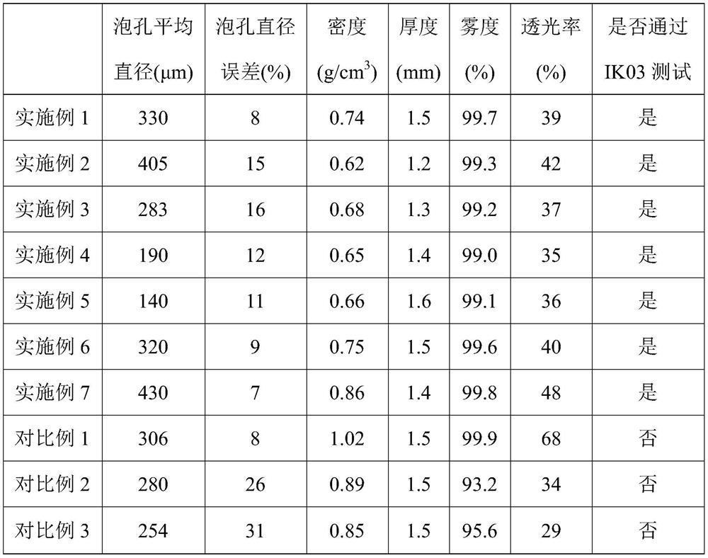
[0054] The performance test of the prepared foamed light diffusion plate was carried out, and the specific results are shown in Table 1.


PUM

PropertyMeasurementUnit
Particle sizeaaaaaaaaaa
Densityaaaaaaaaaa
Cell diameteraaaaaaaaaa

Abstract

The invention relates to a foaming light diffusion plate, a preparation method and application thereof. The preparation method of the foaming light diffusion plate comprises the following steps: mixing and melting polystyrene, a polymer containing carbonyl and a nucleating agent to obtain a blend, wherein the melting temperature of the polymer containing carbonyl is smaller than or equal to 200 DEG C; and injecting supercritical carbon dioxide into the blend, and then extruding and foaming to obtain the foaming light diffusion plate. According to the invention, the preparation method of the foaming light diffusion plate is clean and harmless, the mass of the light diffusion plate can be effectively reduced, and the prepared foaming light diffusion plate is uniform in cell size, uniform in density, good in optical performance and mechanical performance, capable of passing an IK03 protection grade test and wide in application prospect.

Description

technical field [0001] The invention relates to the field of diffusion plates, in particular to a foamed light diffusion plate and its preparation method and application. Background technique [0002] Light diffusion panels are widely used in 5G smartphone industry, automotive coordination industry, liquid crystal display and LED lighting and other fields. The traditional light diffusion plate is a translucent plexiglass plate. On the surface or both surfaces of the plexiglass plate, concave and convex points or concave point stripes are processed, which can improve the light dispersion performance of the light diffusion plate and make the light emitted by the light source pass through the light. The diffuser plate is able to homogenize after emission, achieving a soft and uniform lighting effect. However, the high quality and high density of this plexiglass plate limit its application field. [0003] In order to reduce the quality of the light diffusion plate, a foamed li...

Claims


Application Information

Patent Timeline
IPC IPC(8): C08J9/12C08L25/06C08L67/02C08L33/26C08L77/02C08K3/34C08K3/26C08K3/36C08K3/22C08K3/32G02B5/02
CPCC08J9/122C08J9/0061C08J9/0066G02B5/0247G02B5/0268C08J2203/06C08J2203/08C08J2201/03C08J2325/06C08J2467/02C08J2433/26C08J2477/02Y02P20/54
Inventor 冯虎威赵德为裴旺汪浩立
Owner ZHEJIANG CARBON VISION TECH CO LTD
Why Eureka
Try Eureka