
Device for compensating for voltage or current

A compensation device and current technology, applied in circuit devices, output power conversion devices, measurement devices, etc., can solve the problems of increasing the size and price of current compensation devices, reducing noise reduction performance, and increasing the size of common mode choke coils. , to achieve the effect of weight reduction

Pending Publication Date: 2022-01-07
EM考尔泰克公司 +1
View PDF0 Cites 0 Cited by
  • Summary
  • Abstract
  • Description
  • Claims
  • Application Information

AI Technical Summary

Problems solved by technology

However, in high power / high current systems, the noise reduction performance of common mode (CM) choke coils drops sharply due to the magnetic saturation phenomenon
Therefore, in a high-power / high-current system, in order to prevent magnetic saturation and maintain noise reduction performance, it was necessary to increase the size or number of common mode choke coils in the past, so the current compensation device used for high-power products has occurred. Problems with extreme increases in size and price

Method used


Image

  • Device for compensating for voltage or current
  • Device for compensating for voltage or current
  • Device for compensating for voltage or current

Examples


Embodiment Construction

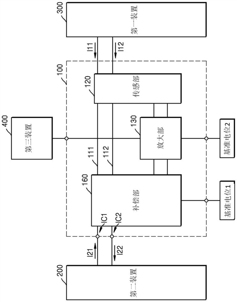
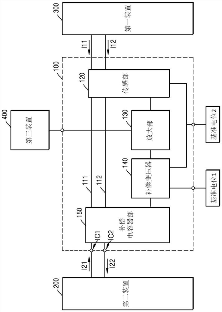
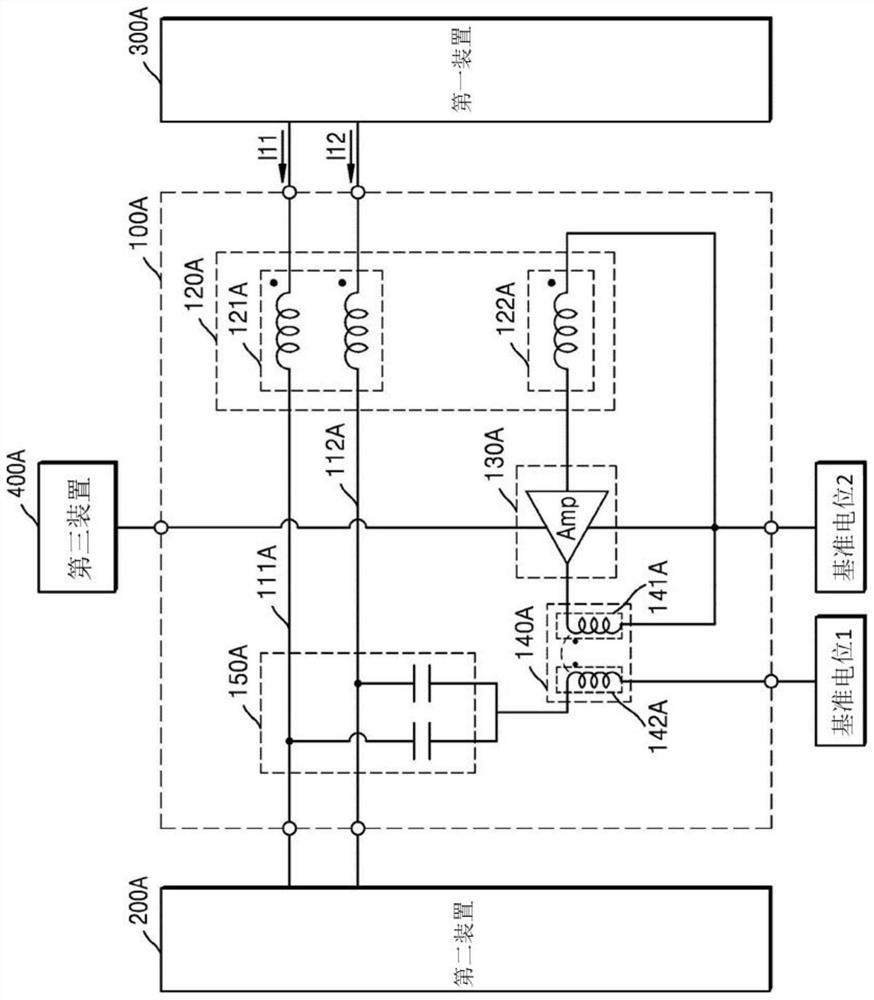
[0086] While the present invention is susceptible to various transformations and embodiments, certain embodiments will be illustrated by way of example in the drawings and described in detail in the text. If referring to the following and attached Figure 1 With the detailed description of the embodiments, the effects and features of the present invention and the method for achieving them will be clarified. However, the present invention is not limited to the examples disclosed below, and can be embodied in various forms.

[0087] Embodiments of the present invention will be described in detail below with reference to the accompanying drawings. When describing with reference to the accompanying drawings, the same or corresponding constituent elements are given the same or the same series of reference numerals, and repeated description thereof will be omitted.

[0088] In the following embodiments, the terms first, second, etc. have no limiting meaning, but are used for the pu...


PUM


Abstract

The present invention provides an active compensation device for actively compensating for a first current input in a common mode to each of at least two high current paths connected to a first device, the active compensation device comprising: the at least two high current paths for transmitting, to the first device, a second current supplied by a second device; a sensing unit for sensing the first current on the high current paths thereby generating an output signal corresponding to the first current; an amplification unit for amplifying the output signal of the sensing unit thereby generating an amplified current; a compensation unit for generating a compensated current on the basis of the amplified current and flowing the compensated current through each of the at least two high current paths; a first disturbance protection unit connected in parallel to an output terminal of the sensing unit from which the output signal is generated; and a second disturbance protection unit connected in parallel to an input terminal of the compensation unit, wherein the first disturbance protection unit and the second disturbance protection unit include transient voltage suppression (TVS) diode elements.

Description

technical field [0001] Embodiments of the present invention relate to an active current (and / or voltage) compensation device, and relate to a method for actively compensating current and / or voltage input in a common mode on more than two large current paths connecting two devices Active type compensation device. Background technique [0002] In general, electrical products for home appliances, industrial electrical products, or electrical equipment such as electric vehicles emit noise during operation. For example, in electronic equipment, noise is released through the power line due to the switching operation of the power conversion device. If this noise is ignored, it will not only be harmful to the human body, but also cause malfunction or failure of peripheral components and other electronic equipment. Electromagnetic interference caused by electronic equipment to other equipment is called EMI (Electromagnetic Interference: Electromagnetic Interference), and the noise ...

Claims


Application Information

Patent Timeline
IPC IPC(8): H02M1/44H03H7/42H03F1/30H03F1/56H02J3/00H01F27/42G01R19/165H02M1/12H01F17/06H01F17/00
CPCH02M1/12H02M1/44H02J3/01H03F3/45475H03F3/45928H03F1/565H03F2203/45528H03F2203/45731H03H7/425H01F27/42H01F38/30H01F2038/305Y02E40/40
Inventor 郑想永金嗔国
Owner EM考尔泰克公司
Learn More