Dry granulation slag storage flow control device and slag storage flow control method

A dry granulation and slag storage technology, applied in the field of metallurgy, can solve the problems of heat loss, inability to carry out granulation treatment, low slag temperature, etc., and achieve the effect of ensuring fluidity, heating efficiency and heating uniformity

Pending Publication Date: 2022-01-11
北京中冶设备研究设计总院有限公司
View PDF7 Cites 0 Cited by
  • Summary
  • Abstract
  • Description
  • Claims
  • Application Information

AI Technical Summary

Problems solved by technology

[0004] In view of the above problems, the purpose of the present invention is to provide a dry granulation slag storage flow control device and a slag flow control method to solve the problem of slag temperature ca

Method used


Image

  • Dry granulation slag storage flow control device and slag storage flow control method
  • Dry granulation slag storage flow control device and slag storage flow control method
  • Dry granulation slag storage flow control device and slag storage flow control method

Examples


Embodiment 1

[0049] The implementation method of this embodiment: Drain 1450°C blast furnace slag directly from the blast furnace through the slag ditch, with a processing capacity of 30t / h.

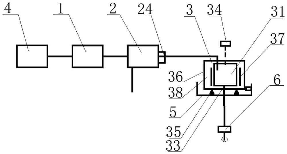
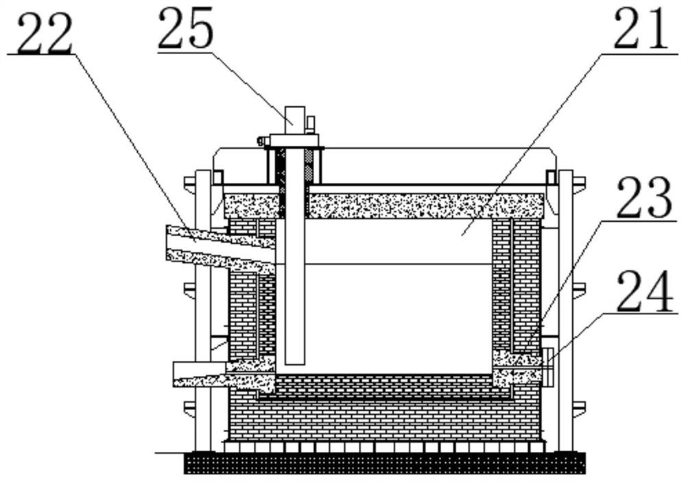
[0050] The volume of the slag storage insulation device 2 is 35m 3 , the slag storage body 21 is built from the inside to the outside by heat-resistant and heat-insulating materials, which are the working layer, heat-insulating layer and heat-insulating layer respectively, and the periphery adopts a metal shell and is supported by a steel structure, and the bottom is arranged in sequence from top to bottom. , Bottom steel plate and supporting steel structure are set under the insulation layer, and the supporting steel structure has good ventilation conditions.

[0051] An AC heating electrode 25 is arranged inside the slag storage main body 21. The number of the AC heating electrodes 25 is three electrodes, and the three electrodes are evenly distributed inside the slag storage main body 21. The powe...

Embodiment 2

[0056] The implementation method of this embodiment: the 1490 ° C blast furnace slag discharged from the blast furnace first flows into the slag tank, and the slag tank is transported to the vicinity of the slag receiving tank, and the slag tank is lifted by a crane, and the molten slag is poured from the slag tank into the slag receiving tank, and then from the slag receiving tank It flows into the slag storage insulation device 2 with a processing capacity of 60t / h.

[0057] The volume of the slag storage insulation device 2 is 35m 3 The slag storage main body 21 is built from heat-resistant and heat-insulating materials from the inside to the outside, which are successively the working layer, the heat-insulating layer and the heat-insulating layer. The periphery is made of a metal shell and supported by a steel structure. Bottom steel plate and supporting steel structure are arranged below, and the supporting steel structure has good ventilation conditions.

[0058] Three ...


PUM


Abstract

The invention provides a dry granulation slag storage flow control device and a slag storage flow control method. The dry granulation slag storage flow control device comprises a molten slag conveying device, a slag storage heat preservation device and a flow control device, wherein the slag storage heat preservation device comprises a slag storage main body; a slag inlet connected with the discharging end of the molten slag conveying device is formed in the upper portion of the side wall of the slag storage main body, a slag outlet is formed in the lower portion of the side wall of the slag storage main body, and a molten slag flow regulation and control structure is arranged at the slag outlet; an electric heating electrode is arranged in the slag storage main body; the flow control device comprises a tank body; a slag inlet is formed in the side wall of the tank body; a water opening is formed in the bottom of the tank body; a radar charge level indicator is arranged above the tank body; and a weighing liquid level meter is arranged at the bottom of the tank body. According to the device and the method, the problems that at present, due to heat loss in the storage and transportation process and the fact that follow-up heat compensation is difficult, the temperature of the molten slag is too low, the fluidity becomes poor, granulation treatment cannot be conducted and the like can be solved; and the flow of slag entering the next procedure can be well controlled.

Description

technical field [0001] The invention relates to the technical field of metallurgy, and more specifically, to a dry granulation slag storage flow control device and a slag storage flow control method. Background technique [0002] High-temperature slag refers to the by-products produced while refining metals in the pyrometallurgical process. The high-temperature liquid slag produced by smelting furnaces such as blast furnaces and submerged arc furnaces is "intermittent"; the slag dry granulation process generally requires a continuous method production, and requires a stable supply of slag, which requires storage and heat preservation of the slag to meet the subsequent granulation requirements of the slag. [0003] At present, the slag is stored in the tundish. When the slag is granulated, the slag is sent out from the tundish through the slag transport tank to buffer the slag. However, due to the use of slag The slag is transported by the transport tank. The transportation ...

Claims


Application Information

Patent Timeline
IPC IPC(8): C21B3/10C21B3/06H05B3/03H05B3/62
CPCC21B3/10C21B3/06H05B3/03H05B3/62Y02W30/50
Inventor 张金良张富信黄超马超宇朱立江黄忠源刘猛柏赟张杰马煜真
Owner 北京中冶设备研究设计总院有限公司
Why Eureka
Try Eureka