Microscopic imaging device

A technology for microscopic imaging and microscopic equipment, which is used in measurement devices, material excitation analysis, fluorescence/phosphorescence, etc., and can solve problems such as long excitation windows and inaccessibility

Pending Publication Date: 2022-01-11
SHENZHEN UNIV
View PDF18 Cites 1 Cited by
  • Summary
  • Abstract
  • Description
  • Claims
  • Application Information

AI Technical Summary

Problems solved by technology

[0004] The technical problem to be solved by the present invention is to provide a microscopic imagin

Method used


Image

  • Microscopic imaging device

Examples


Embodiment approach

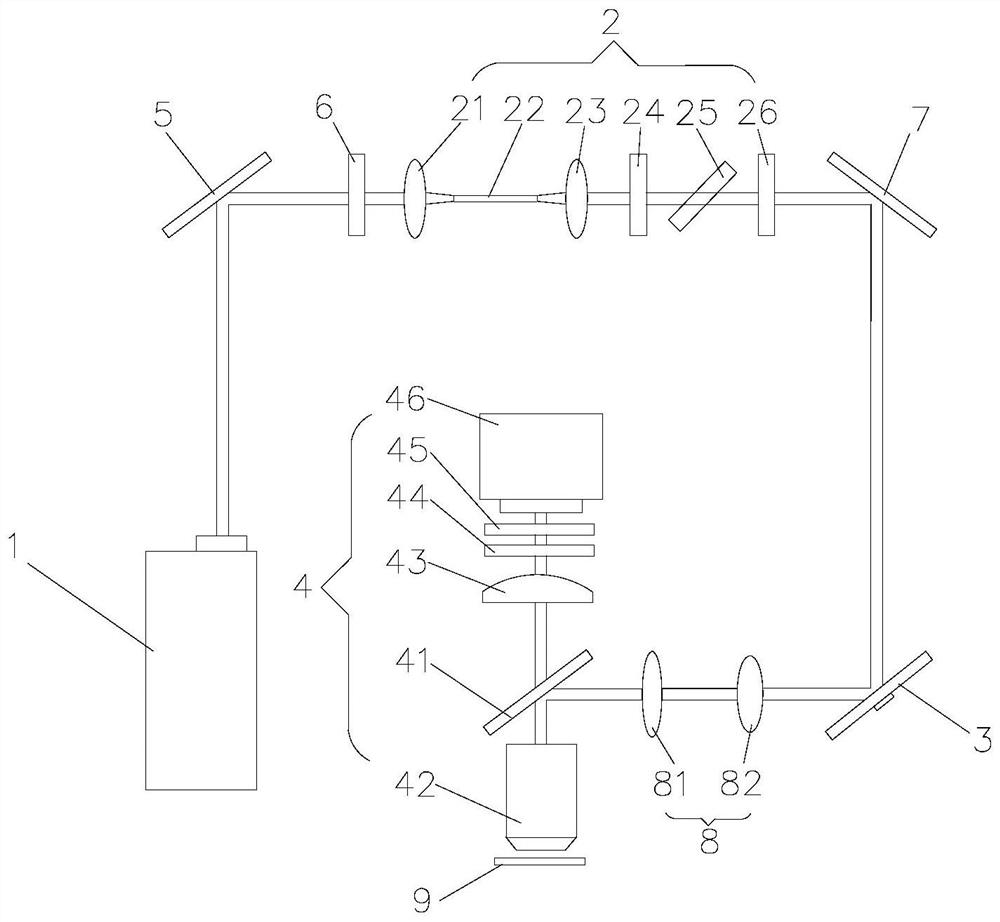
[0040] see figure 1 , in this embodiment, the microscopic imaging device includes a laser generator 1 for generating laser light, and a first mirror 5 arranged in sequence along the optical path of the laser light, a half-wave plate 6, a frequency modulation device 2, and a second mirror 7. Scanning galvanometer device 3, beam expander collimating mirror group 8 and microscopic device 4; frequency modulation device 2 includes coupling lens 21, polarization maintaining large mode field optical fiber 22, decoupling lens 23, First optical filter 24, germanium sheet 25, medium density attenuation sheet 26; Fluorescence microscope equipment 4 comprises the objective lens assembly 42 with optical axis, and the dichroic mirror 41 that is arranged along the optical axis of objective lens assembly 42, short-focus lens 43, the second optical filter 44, the third optical filter 45 and the photosensor 46, the sample 9 is arranged on one side of the objective lens assembly 42, the dichroic...


PUM


Abstract

The invention provides a microscopic imaging device. The microscopic imaging device comprises a laser generator for generating laser, and frequency modulation equipment, scanning galvanometer equipment and microscopic equipment which are sequentially arranged along a light path of the laser, the frequency modulation device comprises a coupling lens, an optical fiber, a decoupling lens, a first optical filter, a germanium sheet and a medium-density attenuation sheet which are sequentially arranged along the optical path of the laser. The soliton self-frequency-shift effect of the laser in the optical fiber is utilized, after the laser generates frequency shift in the polarization-maintaining large-mode-field optical fiber, the first optical filter is used for selecting the frequency of the laser, and then the laser with the corresponding frequency and wavelength is obtained and used for laser scanning microscopy.

Description

technical field [0001] The invention belongs to the technical field of microscopic imaging, and in particular relates to a microscopic imaging device. Background technique [0002] The brain is a complex environment made up of blood vessels and different cells. To decipher information about brain function, various imaging modalities have been developed. Among them, multiphoton microscopy (MPM) occupies a unique niche due to its noninvasiveness, subcellular resolution, functional and dynamic tracking capabilities, and deep tissue penetration. This makes MPM an indispensable technique for deep brain imaging with high spatiotemporal resolution. [0003] Improving depth is the goal of any imaging technique, and during the development of the MPM, two measures were taken to achieve this goal: (1) Use 3PM to better suppress the surface background so that the signal-background ratio of the information at the focal point to be resolved is (SBR) greater than unity. (2) Use a longe...

Claims


Application Information

Patent Timeline
IPC IPC(8): G01N21/64G01N21/01
CPCG01N21/6402G01N21/01
Inventor 王科邱娉陈新林仝申
Owner SHENZHEN UNIV
Why Eureka
Try Eureka