Omnidirectional antenna and antenna housing

An omnidirectional antenna and axis technology, applied in the field of communication, can solve the problems of deteriorating system electromagnetic compatibility and radar scattering cross section, horizontal plane gain drop, antenna crowding, etc., and achieve good omnidirectional radiation performance, easy implementation, and wide impedance bandwidth Effect

Pending Publication Date: 2022-01-11
KUANG CHI CUTTING EDGE TECH LTD
View PDF0 Cites 0 Cited by
  • Summary
  • Abstract
  • Description
  • Claims
  • Application Information

AI Technical Summary

Problems solved by technology

Mounting multiple antennas in a limited space will inevitably cause crowding between different types of antennas, deteriorating the electromagnetic compatibility and radar cross-section of the system, resulting in a downward tilt of the radiation pattern, and will also increase with the increase in operating frequency And further deterioration, the radiation pattern is no longer symmetrical about the horizontal plane, and the gain of the horizontal plane is greatly reduced

Method used


Image

  • Omnidirectional antenna and antenna housing
  • Omnidirectional antenna and antenna housing
  • Omnidirectional antenna and antenna housing

Examples


Embodiment Construction

[0029] The following will clearly and completely describe the technical solutions in the embodiments of the present invention with reference to the accompanying drawings in the embodiments of the present invention. Obviously, the described embodiments are only some, not all, embodiments of the present invention. Based on the embodiments of the present invention, all other embodiments obtained by persons of ordinary skill in the art without creative efforts fall within the protection scope of the present invention.

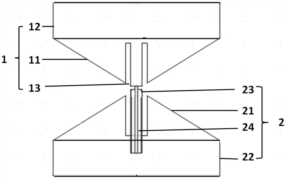
[0030] figure 1 It is a schematic cross-sectional structure diagram of an omnidirectional antenna of the present invention. figure 1 Among them, an omnidirectional antenna includes: a first cone 1 and a second cone 2, both of which are composed of a frustum of a cone and a cylinder.

[0031] The first cone 1 includes a first frustum 11 and a first cylinder 12, and the second cone 2 includes a second frustum 21 and a second cylinder 22, wherein the top of the first...


PUM


Abstract

The invention provides an omnidirectional antenna. The omnidirectional antenna comprises a first cone and a second cone, the first cone comprises a first circular truncated cone part and a first cylinder, and the second cone comprises a second circular truncated cone part and a second cylinder, wherein the top of the first circular truncated cone part and the top of the second circular truncated cone part are close to each other and are oppositely arranged, the bottom of the first circular truncated cone part is connected with the first cylinder, and the bottom of the second circular truncated cone part is connected with the second cylinder. The antenna has a stable horizontal omnidirectional radiation characteristic, and is simple in structure and easy to implement.

Description

【Technical field】 [0001] The invention relates to the technical field of communications, in particular to an omnidirectional antenna and a radome. 【Background technique】 [0002] Antennas play an extremely important role as the front end of modern wireless systems such as radar, communication, navigation, and remote sensing. With the development of modern information technology, people have put forward higher requirements on the performance of the antenna, hoping that it will have excellent performance in terms of electrical performance such as pattern, gain, and working bandwidth. At the same time, with the continuous development and innovation of integrated technology and miniaturization technology, higher requirements are put forward for the miniaturization and portability of the antenna structure. In some narrow application scenarios, in order to realize the transmission and reception of electromagnetic waves in different frequency bands, there are often scenes with mul...

Claims


Application Information

Patent Timeline
Patent Type & Authority Applications(China)
IPC IPC(8): H01Q1/36H01Q1/52H01Q1/42
CPCH01Q1/36H01Q1/52H01Q1/42
Inventor 刘若鹏赵治亚周劲波
Owner KUANG CHI CUTTING EDGE TECH LTD
Why Eureka
Try Eureka