
Method and device for in-situ remediation of groundwater pollution by electrically driven biological PRB (permeable reactive barrier)

A groundwater pollution and in-situ remediation technology, which is applied in biological water/sewage treatment, water pollutants, electrochemical and biological combined treatment, etc., can solve problems such as limited remediation effect, limited effect of groundwater pollution remediation, and increased cost

Active Publication Date: 2022-01-14
CHONGQING UNIV
View PDF7 Cites 4 Cited by
  • Summary
  • Abstract
  • Description
  • Claims
  • Application Information

AI Technical Summary

Problems solved by technology

Among them, the method of injecting oxygen (air) is usually low in efficiency and high in cost; the method of adding electron acceptors such as nitrates and sulfates to groundwater by injection or slow release, due to the short residence time of the added electron acceptors, the utilization efficiency Low, need regular replenishment to maintain biodegradation, and as a class of environmental pollutants, it is easy to cause secondary pollution, long-term monitoring, maintenance and input of materials and energy further increase its cost and limit its engineering application
Moreover, this method has limited remediation effect on oxidative pollutants such as halogenated hydrocarbons and nitrates.
[0006] In addition, the method of adding exogenous electron acceptors through injection wells or seepage channels, etc., the distribution and transfer of electron acceptors are mainly restricted by geological conditions, injection well locations and injection well layouts, and the effect on groundwater pollution restoration is limited.
In order to treat larger areas, more injection wells and higher injection frequency are usually required, increasing its cost

Method used


Image

  • Method and device for in-situ remediation of groundwater pollution by electrically driven biological PRB (permeable reactive barrier)
  • Method and device for in-situ remediation of groundwater pollution by electrically driven biological PRB (permeable reactive barrier)
  • Method and device for in-situ remediation of groundwater pollution by electrically driven biological PRB (permeable reactive barrier)

Examples


Embodiment 1

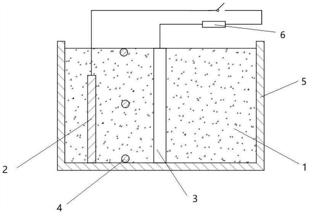
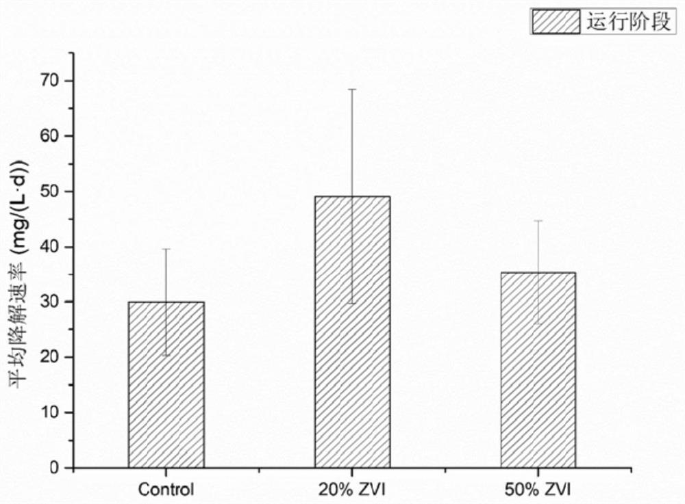
[0043] Such as figure 1 As shown, the permeable reaction wall 1 is set as a cylinder, and its volume is Φ75 mm × 100 mm. The cylindrical permeable reaction wall 1 is filled with a mixed filler of 140g of conductive carbon material and 28g of zero-valent iron material, wherein the mass ratio of conductive carbon material and zero-valent iron material is 20%. The conductive carbon material uses graphite particles with a particle size of 2-4mm and a density of 2.1-2.3g cm-3; the zero-valent iron material uses zero-valent iron particles with a particle size of 2mm and a density of 3.5-4.0g cm-3 . A carbon rod with a volume of Φ5 mm × 100 mm is inserted into the permeable reaction wall 1 as the anode 2, and the permeable reaction wall 1, anode 2 and microorganisms together constitute the anode area of ​​the biological PRB.

[0044] An air cathode was inserted in the center of the bio-PRB anode area as the cathode 3, the volume of the air cathode was Φ20 mm × 100 mm, and platinum ...

Embodiment 2

[0048] The filler of the permeable reaction wall 1 is: a mixed filler of 140g of conductive carbon material and 70g of zero-valent iron material, the mass ratio of conductive carbon material and zero-valent iron material is 50%, and the rest of the components are the same as in Example 1.

[0049] In the control group, the filler of the permeable reaction wall 1 is 140g of conductive carbon material without zero-valent iron material, and the rest is the same as that of Example 1.

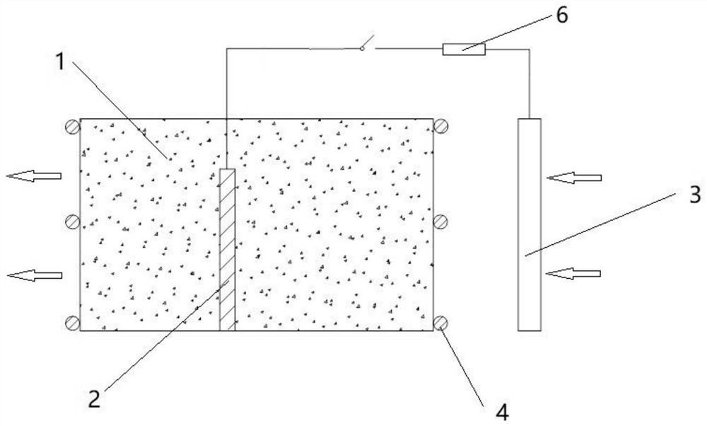
[0050] The device of the present invention can adjust the shape, structure and position of the permeable reaction wall 1, the anode 2, the cathode 3, the water-conducting wall 4, the external circuit element 6 and the final reactor 5 according to the environment.

Embodiment 3

[0052] As an embodiment of the device of the present invention, such as figure 2 As shown, the anode 2 is inserted into the permeable reaction wall 1, and the permeable reaction wall 1, anode 2 and microorganisms together constitute the anode area of ​​the biological PRB. The cathode 3 is installed at the water inlet end of the bio-PRB anode area, and a water-conducting wall 4 is set between the bio-PRB anode area and the cathode 3, and a water-conducting wall 4 is also provided at the water outlet of the bio-PRB anode area. The external circuit element 6 is a power supply; the cathode 3 is connected to the negative electrode of the external circuit element 6 through a copper wire, and the anode area of ​​the biological PRB is connected to the positive electrode of the external circuit element 6 through an anode.


PUM

PropertyMeasurementUnit
Particle sizeaaaaaaaaaa

Abstract

The invention discloses a method and a device for in-situ remediation of groundwater pollution by electrically driven biological PRB (permeable reactive barrier). The device comprises a PRB, microorganisms, an anode, a cathode and an external circuit element device, the anode is mounted in the PRB and forms a biological PRB anode region together with the microorganisms; a water guide wall is arranged between the biological PRB anode region and the biological PRB cathode for separation; the cathode and the anode are connected with an external circuit element to jointly form an external circuit; the external circuit adopts closed-open-closed cycle operation, and generates and regenerates an iron oxide oxidation zone and an iron oxide reduction zone in situ according to pollutant properties and water quality requirements; and a filler of the PRB is a mixed filler of a conductive carbon material and a zero-valent iron material, and the mass ratio of the conductive carbon material to the zero-valent iron material is 0.1%-50%. According to the method provided by the invention, underground water petroleum hydrocarbon, halogenated hydrocarbon and nitrate pollution can be remarkably resolved, the cost is low, and the risk of secondary pollution does not exist.

Description

technical field [0001] The invention relates to a method and a device for repairing groundwater pollution in situ by electric drive biological PRB, and belongs to the technical field of groundwater pollution control and restoration. Background technique [0002] With the development of the petrochemical industry, during the exploitation of petroleum, the processing, storage, transportation, and use of petroleum and petrochemical products, and the treatment and disposal of related wastewater, the groundwater pollution caused by accidental leakage of pipelines and storage tanks and the discharge of wastewater has been It is a major environmental problem, including petroleum hydrocarbons, petroleum hydrocarbon derivatives and halogenated hydrocarbons, most of which are teratogenic, carcinogenic, mutagenic and biologically toxic. In addition, the excessive use of agricultural chemical fertilizers, discharge of domestic sewage and industrial wastewater, sewage irrigation and over...

Claims


Application Information

Patent Timeline
IPC IPC(8): C02F3/00C02F3/34C02F103/06C02F101/16C02F101/32C02F101/36
CPCC02F3/005C02F3/34C02F2103/06C02F2201/46105C02F2101/163C02F2101/32C02F2101/36
Inventor 张代钧寇双伍杨芳芳张峻通
Owner CHONGQING UNIV
Learn More