Negative pressure exhaust system for garbage station

A technology of garbage station and negative pressure fan, which is applied in sanitary equipment for toilets, dispersed particle filtration, gas treatment, etc. It can solve problems such as inability to spray, bacteria breeding in garbage, and staff slipping during water stain residence time. Shorten the residence time, accelerate the drying speed, and have good antibacterial and deodorizing effects

Pending Publication Date: 2022-01-14
苏州捷嘉环保科技有限公司
View PDF0 Cites 0 Cited by
  • Summary
  • Abstract
  • Description
  • Claims
  • Application Information

AI Technical Summary

Problems solved by technology

[0004] Based on this, the purpose of the present invention is to provide a negative pressure exhaust system for garbage stations to solve the problem that the existing negative pressure exhaust system for garbage stations has a simple structure and uses a negative pressure fan to suck the outside air into the garbage station. Since the temperature of the outside air may be higher when the outside air enters the garbage station, the extracted hot air may cause the accumulated garbage to breed bacteria, and the odor cannot be suppressed, and the existing garbage station uses a negative pressure exhaust system It is impossible to spray the garbage piled in the garbage station to achieve the purpose of deodorization and disinfection, and the existing garbage station often leaves some water stains on the ground after the garbage is piled up. In addition, the negative pressure exhaust system used in the existing garbage station cannot purify the internal air after the garbage is transferred, and the internal smell of the garbage station always affects the technical problems of the surrounding residents.

Method used


Image

  • Negative pressure exhaust system for garbage station
  • Negative pressure exhaust system for garbage station
  • Negative pressure exhaust system for garbage station

Examples


Embodiment Construction

[0027] The following will clearly and completely describe the technical solutions in the embodiments of the present invention with reference to the drawings in the embodiments of the present invention. The embodiments described below by referring to the figures are exemplary only for explaining the present invention and should not be construed as limiting the present invention.

[0028] The embodiments of the present invention will be described below according to the overall structure of the present invention.

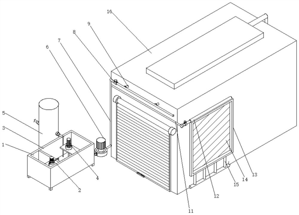
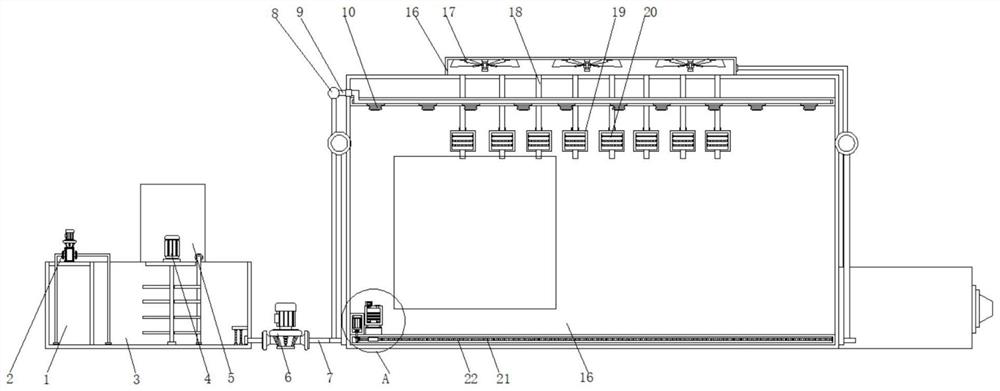
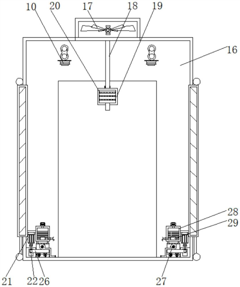
[0029] see Figure 1-6, a negative pressure exhaust system for a garbage station, comprising a raw liquid bin 1, a metering pump 2 is arranged on the top of the raw liquid bin 1, and a mixing bin 3 is arranged on one side of the raw liquid bin 1, between the raw liquid bin 1 and the mixing bin 3 A partition is provided, and a filter screen is provided inside the mixing chamber 3, and the number of the filter screens is two groups, and the two groups of filter screens ...


PUM


Abstract

The invention discloses a negative pressure exhaust system for a garbage station, and relates to the field of garbage station purification. The negative pressure exhaust system comprises a stock solution bin, the top end of the stock solution bin is provided with a metering pump, one side of the stock solution bin is provided with a mixing bin, the top end of the mixing bin is provided with a stirrer, one side of the mixing bin is provided with a water tower, and the outer side of the mixing bin is provided with a water pump. Through arrangement of a second branch pipe, a connecting pipe, a frame body, a water curtain, a drainage pipe, the garbage station, a negative pressure fan, an exhaust pipe, a cleaning barrel and a first filter screen, when the negative pressure fan is used for exhausting air, external air enters the garbage station and firstly passes through the water curtain, the water curtain is a wetted honeycomb-shaped paper core, after the air passes through the water curtain, the temperature of the air can be reduced, the air inlet temperature is reduced, so that the overall temperature in the garbage station is controlled, bacteria breeding of garbage stacked in the garbage station due to too high temperature is avoided, and a certain odor inhibiting effect can be achieved under the condition that the temperature is relatively low.

Description

technical field [0001] The invention relates to the field of purification of garbage stations, in particular to a negative pressure exhaust system for garbage stations. Background technique [0002] Garbage station refers to the place where garbage is stored or recycled, residential areas, factories and other living areas, residents, housing construction and other domestic garbage transfer stations, mainly used for temporary stacking of garbage, and then regularly transferred to large-scale garbage disposal by garbage trucks such as garbage transfer vehicles station or landfill. [0003] The existing negative pressure exhaust system for garbage stations has a simple structure, using a negative pressure fan to suck the outside air into the garbage station. However, when the outside air enters the garbage station, the temperature of the outside air may be higher, so the extraction The hot air may cause the accumulated garbage to breed bacteria, and the odor cannot be suppress...

Claims


Application Information

Patent Timeline
Patent Type & Authority Applications(China)
IPC IPC(8): E04H1/12B01D53/04B01D46/12F04D25/08A61L2/22A61L2/26A61L9/14A61L11/00
CPCE04H1/1205B01D53/04B01D46/0036B01D46/12F04D25/08A61L2/22A61L2/26A61L11/00A61L9/14B01D2253/102B01D2257/90
Inventor 程保道程明松谢中勇刘敏
Owner 苏州捷嘉环保科技有限公司
Why Eureka
Try Eureka