
Device and method of laser compression bonding for semiconductor chip

A semiconductor and chip technology, applied in laser compression bonding equipment and fields of semiconductor chips, can solve problems such as thermal stress that is not easy to solve

Pending Publication Date: 2022-01-14
SUZHOU MI EQUIP CO LTD
View PDF10 Cites 0 Cited by
  • Summary
  • Abstract
  • Description
  • Claims
  • Application Information

AI Technical Summary

Problems solved by technology

However, it is not easy to solve the problem of thermal stress with existing laser joining / welding technology

Method used


Image

  • Device and method of laser compression bonding for semiconductor chip
  • Device and method of laser compression bonding for semiconductor chip
  • Device and method of laser compression bonding for semiconductor chip

Examples


Embodiment Construction

[0034] Preferred embodiments of the present invention will be described in detail below with reference to the accompanying drawings.

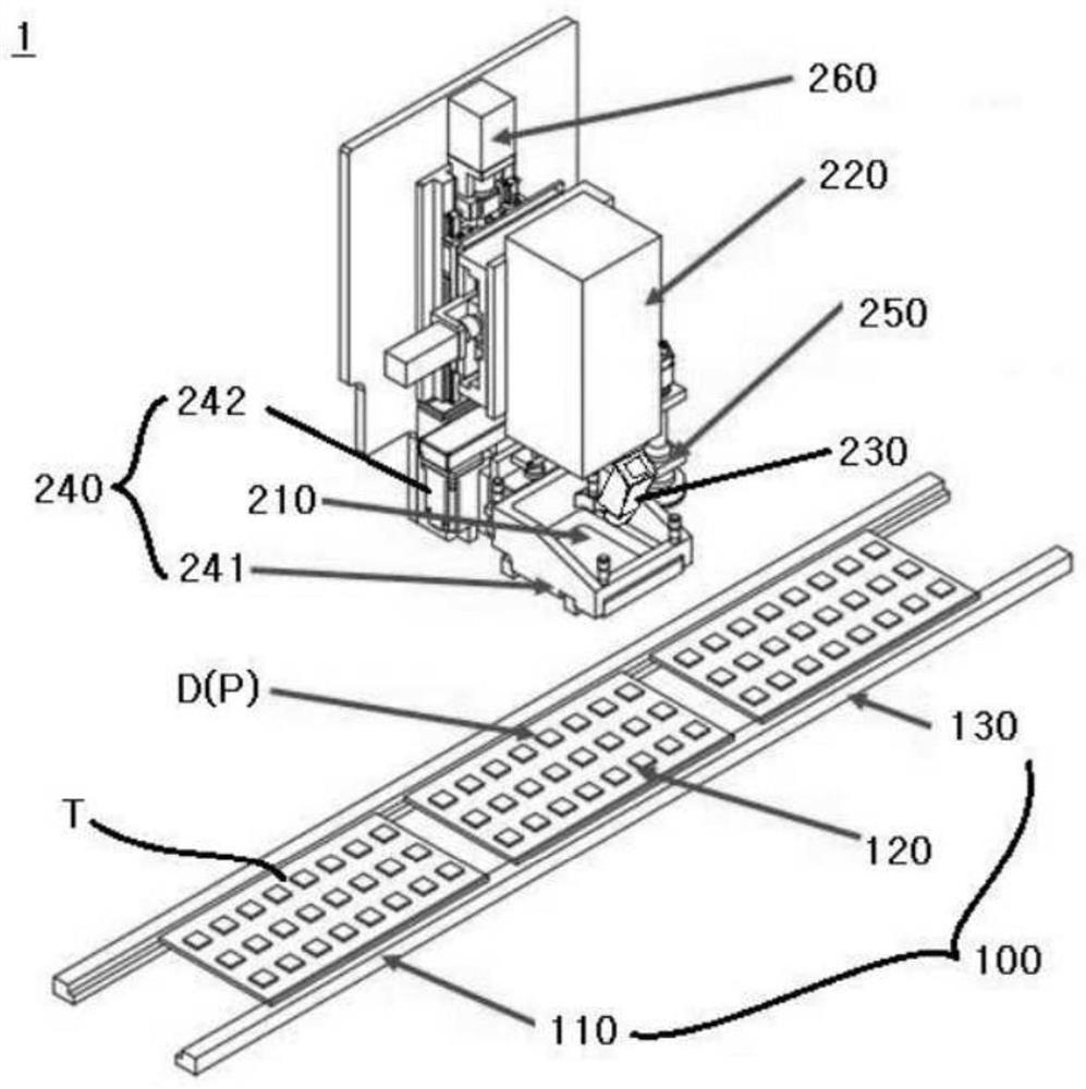
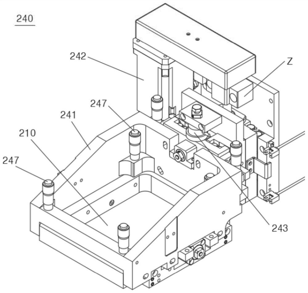
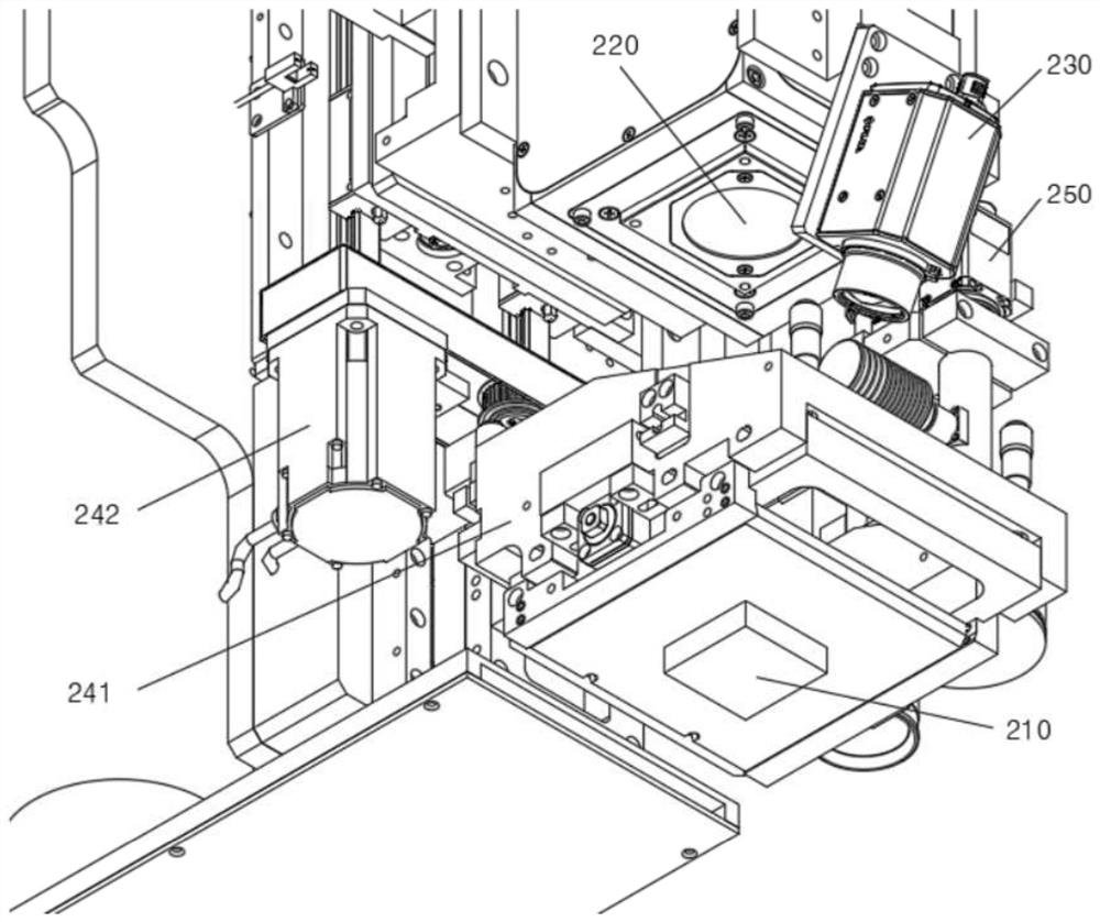
[0035] figure 1 A schematic configuration of a laser compression bonding apparatus according to the present invention is illustrated. figure 2 Illustrated in enlarged form figure 1 The lower part of the joint head in. image 3 Illustrated in enlarged form figure 1 in the bottom of the lower part of the engagement head.

[0036] As shown in the figure, the laser compression bonding apparatus 1 according to the present invention includes a conveyor unit 100 and a bonding head 200 . The conveyor unit 100 is configured to transfer the semiconductor chip (die) D and the substrate P from the pre-bonding area 110 to the unloading area 130 through the main bonding area 120 . The semiconductor chip D and the substrate P are received in the pre-bonding area 110 .

[0037]The bonding head 200 includes a bonding tool 210 , a laser beam generator 220...


PUM


Abstract

The invention discloses a device and method of laser compression bonding for semiconductor chips. The device and method of laser compression bonding for semiconductor chips are proposed. The device includes a conveyor unit(100) that transports a semiconductor chip and a substrate, and a bonding head(200) that includes a bonding tool(210) for applying a pressure to the chip and substrate, a laser beam generator(220) for emitting a laser beam, a thermal imaging camera(230) for measuring temperatures of the surfaces of semiconductor chip and substrate, and a compression unit(240) for controlling a pressure applied by the bonding tool and a position thereof, wherein the compression unit(240) includes a mount(241) on which the bonding tool is detachably mounted, and a servo motor(242) and a load cell(243) that apply a pressure to the mount(241) or control a position thereof. The servo motor(242) is controlled with two values for pressure application and positioning.

Description

[0001] Cross References to Related Applications [0002] This application claims priority from Korean Patent Application No. 10-2020-0087077 filed on July 14, 2020, the entire contents of which are hereby incorporated by reference for all purposes. technical field [0003] The present invention relates to a laser compression bonding apparatus and a laser compression bonding method for bonding a semiconductor chip having a size of 100 microns or less to a substrate, and particularly, to bonding a semiconductor chip to a substrate while controlling pressure applied by a bonding tool and A laser compression bonding apparatus and a laser compression bonding method that control its position to effectively suppress warping of a semiconductor chip and a substrate that occurs when performing laser bonding. Background technique [0004] In general, a flipchip bonding process is performed by subjecting a bump structure called lead-free solder or Cu pillar to convection reflow. An exp...

Claims


Application Information

Patent Timeline
Patent Type & Authority Applications(China)
IPC IPC(8): H01L21/603B23K26/03B23K26/21B23K26/70
CPCH01L24/75H01L24/81B23K26/21B23K26/702B23K26/032B23K26/034H01L2224/75001H01L2224/75263H01L2224/753H01L2224/75313H01L2224/75821H01L2224/75841H01L2224/759H01L2224/7592H01L2224/81203H01L2224/81224H01L2224/81801B23K2101/40H01L2924/3511H01L2224/81908H01L2224/75901H01L2224/7565H01L2224/75262H01L2224/75251H01L2224/131H01L24/16H01L24/13H01L2224/16227B23K26/0838H01L2924/014H01L2924/00014H01L23/562H04N5/33B23K26/20
Inventor 朴宰伸胡光荣
Owner SUZHOU MI EQUIP CO LTD
Learn More