Frequency double-chirp microwave waveform generation method and device

A technology for generating equipment and methods, which is applied in the fields of optics and microwaves, can solve problems such as signal bandwidth limitations, and achieve the effect of fast scanning

Pending Publication Date: 2022-01-14
HUAZHONG UNIV OF SCI & TECH
View PDF5 Cites 1 Cited by
  • Summary
  • Abstract
  • Description
  • Claims
  • Application Information

AI Technical Summary

Problems solved by technology

Although these methods can generate chirped microwave signals with relatively high frequencies, because they still use electronic equipment and are restricted by electronic bottlenecks, the bandwidth of the generated signals is greatly limited.

Method used


Image

  • Frequency double-chirp microwave waveform generation method and device
  • Frequency double-chirp microwave waveform generation method and device
  • Frequency double-chirp microwave waveform generation method and device

Examples


Embodiment Construction

[0045] In order to make the object, technical solution and advantages of the present invention clearer, the present invention will be further described in detail below in conjunction with the accompanying drawings and embodiments. It should be understood that the specific embodiments described here are only used to explain the present invention, not to limit the present invention. In addition, the technical features involved in the various embodiments of the present invention described below can be combined with each other as long as they do not constitute a conflict with each other.

[0046] In the present invention, the terms "first", "second" and the like in the present invention and the drawings are used to distinguish similar objects, and are not necessarily used to describe a specific order or sequence.

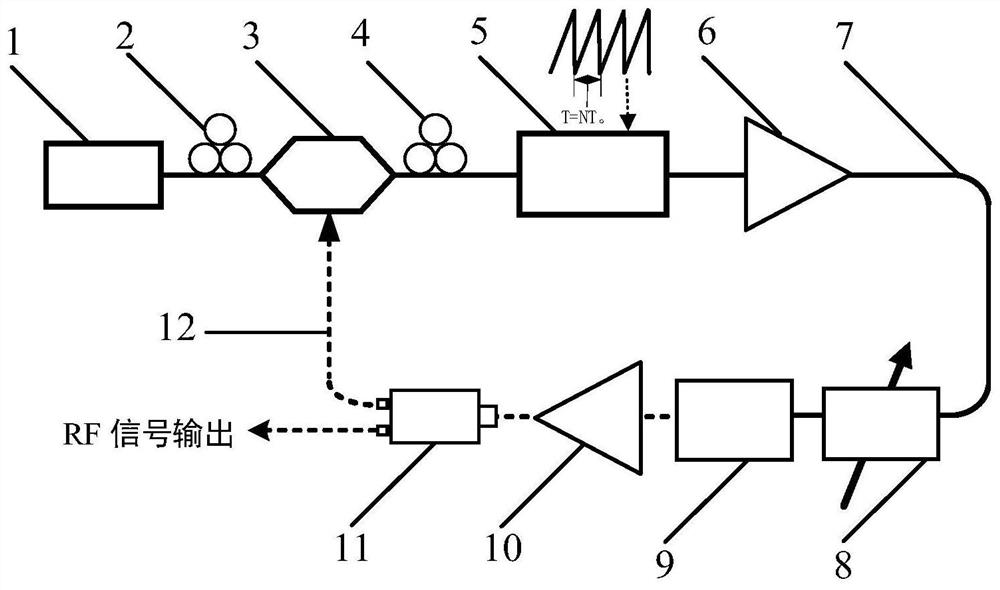
[0047] Such as figure 1 As shown, the present invention provides a kind of frequency double-chirped microwave waveform generating equipment, mainly comprising:

[004...


PUM


Abstract

The invention discloses a frequency double-chirp microwave waveform generation method and device, and belongs to the technical field of optics and microwaves. The method comprises the following steps: S1, generating an optical carrier and a modulation signal, and performing phase modulation on the optical carrier to generate first-order sideband phase modulation signals with the same amplitude and opposite phases; S2, filtering a first-order sideband of the phase modulation signal to realize conversion from phase modulation to intensity modulation; S3, enabling the frequency change period of the phase modulation signal without the first-order sideband to be synchronous with the loop time of the phase modulation signal in the photoelectric oscillation loop or to be integral multiples of the loop time, and achieving Fourier domain mode locking; S4, converting the phase modulation signal with one first-order sideband filtered out into a dual-passband microwave signal after delayed energy storage, dividing the dual-passband microwave signal into two paths, taking one path as a modulation signal to form a photoelectric oscillation loop, and taking the other path as a radio frequency signal to be output. The device provided by the invention realizes the generation of multi-band linear double-chirp microwave waveforms with continuous and tunable frequency.

Description

technical field [0001] The invention belongs to the field of optics and microwave technology, and more specifically relates to a method and equipment for generating frequency double-chirped microwave waveforms. Background technique [0002] The Optoelectronic Oscillator (OEO) uses low-loss optical fiber as the energy storage element, so that the delayed energy storage process is completed in the optical domain. Based on the positive feedback loop of the photoelectric hybrid, the optical signal is directly converted into a microwave signal. High spectral purity overcomes the defect of traditional microwave oscillators that the phase noise deteriorates significantly as the frequency of the oscillating signal increases. In OEO, the optical signal sent by the laser is used as the carrier of the microwave signal, and the microwave signal is loaded into the optical domain through the electro-optical modulator, and then stored in the long optical fiber for time-delay energy, after ...

Claims


Application Information

Patent Timeline
Patent Type & Authority Applications(China)
IPC IPC(8): H04B10/548H04B10/54H04B10/50
CPCH04B10/548H04B10/54H04B10/503
Inventor 于源王琳勾韦磊张新亮
Owner HUAZHONG UNIV OF SCI & TECH
Why Eureka
Try Eureka