Multi-stage piston hydraulic tension oil cylinder

A technology of oil cylinder and piston, which is applied in the field of multi-stage piston hydraulic tension cylinder, which can solve the problems of damage to oil cylinder parts, affect the use of oil cylinder, reduce the working efficiency of oil cylinder, etc., and achieve the effects of reducing damage, improving lubrication effect and reducing aggregation

Pending Publication Date: 2022-01-18
刘铁军
View PDF1 Cites 2 Cited by
  • Summary
  • Abstract
  • Description
  • Claims
  • Application Information

AI Technical Summary

Problems solved by technology

[0004] In this invention, a multi-stage piston hydraulic tension cylinder, mounting seat, movable chamber, through hole, movable plate, threaded rod, nut, fixed rod, fixed hole, positioning groove, positioning block, first locking tooth, second locking tooth, There are many transmission structures such as limit slots, limit rods and springs, so mechanical friction will inevitably occur. When the multi-stage hydraulic cylinder is powered by an engine, it is difficult to lubricate the inside of the cylinder in time, and it is easy to lubricate the inside of the cylinder. damage to the components, which will affect the use of the cylinder and reduce the working efficiency of the cylinder

Method used


Image

  • Multi-stage piston hydraulic tension oil cylinder
  • Multi-stage piston hydraulic tension oil cylinder
  • Multi-stage piston hydraulic tension oil cylinder

Examples


Embodiment approach

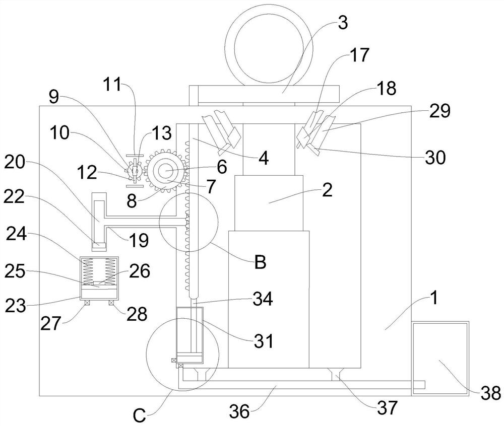
[0044] As an embodiment of the present invention, refer to image 3 , the blowing mechanism includes an air box 23 fixedly installed inside the housing 1, two No. The slider 25 that is fixedly connected, the top of the slider 25 is fixedly installed with the second magnet 26 that cooperates with the first magnet 22, the bottom of the gas box 23 is provided with a first check valve 27, and the bottom of the gas box 23 is provided with a second magnet. The one-way valve 28 is fixed with two air outlet pipes 29 matched with the second one-way valve 28 on the inner wall of the top of the housing 1 , and two air outlets 30 are connected to one end of the two air outlet pipes 29 respectively.

[0045] When the first magnet 22 rotates, when the first magnet 22 reaches the bottom end, it will cooperate with the second magnet 26. According to the principle that the magnets repel each other with the same sex and the opposite sex attracts each other, the second magnet 26 is pushed, and t...


PUM


Abstract

The invention relates to the technical field of hydraulic tension oil cylinders, in particular to a multi-stage piston hydraulic tension oil cylinder which comprises a shell, wherein an oil cylinder body is fixedly mounted on the inner side wall of the bottom of the shell, a limiting plate is fixedly mounted at the top of the oil cylinder body, a rack is fixedly mounted on one side of the oil cylinder body, a control panel is arranged on one side of the shell; a first rotating rod is rotatably mounted on the inner side wall of the shell, a power generation mechanism matched with the rack is arranged in the shell. The rack moves to drive a first gear to drive a second gear to rotate on a second rotating rod, then a coil is driven to cut a magnetic induction line between two magnets, then current is generated; the generated current is transmitted to an electromagnetic valve through a commutator, the electromagnetic valve is started to enable lubricating oil in an oil tank to flow, and finally the lubricating oil arrives at a spray head to lubricate the oil cylinder in time, so that large damage to parts in the oil cylinder caused by abrasion is reduced.

Description

technical field [0001] The invention relates to the technical field of hydraulic tension cylinders, in particular to a multistage piston hydraulic tension cylinder. Background technique [0002] Hydraulic cylinder, which is generally composed of cylinder body, piston, piston rod and cylinder head, etc. The hydraulic cylinder is the actuator in the hydraulic system. The hydraulic system is driven by the prime mover to drive the hydraulic pump, and the hydraulic pump drives the hydraulic cylinder to move. The prime mover These include electric motors powered by electricity and engines powered by oil. [0003] Existing patent (notification number: CN112065815A) a multi-stage piston hydraulic tension cylinder, including a base, the upper surface of the base is fixedly connected with an oil cylinder mechanism, and the base is symmetrically provided with two supports with respect to the cylinder mechanism. A spring mechanism is provided inside the two supporting mechanisms. When ...

Claims


Application Information

Patent Timeline
Patent Type & Authority Applications(China)
IPC IPC(8): F15B15/16F15B15/20F16N7/02F16N23/00B08B5/02B08B13/00H02K1/22H02K1/17
CPCF15B15/16F15B15/1423F16N7/02F16N23/00B08B5/02B08B13/00H02K1/22H02K1/17F16N2280/02
Inventor 刘铁军王智
Owner 刘铁军
Why Eureka
Try Eureka