Intelligent sowing and fertilizing machine suitable for intercropping planting
A fertilizer and intelligent technology, applied in the field of intelligent seeding and fertilizing machines, can solve the problems of inability to achieve staggered planting and no fertilization function, and achieve the effects of maintaining humidity, reducing disturbance, and improving work efficiency
- Summary
- Abstract
- Description
- Claims
- Application Information
AI Technical Summary
Problems solved by technology
Method used
Image

Examples
Embodiment 1
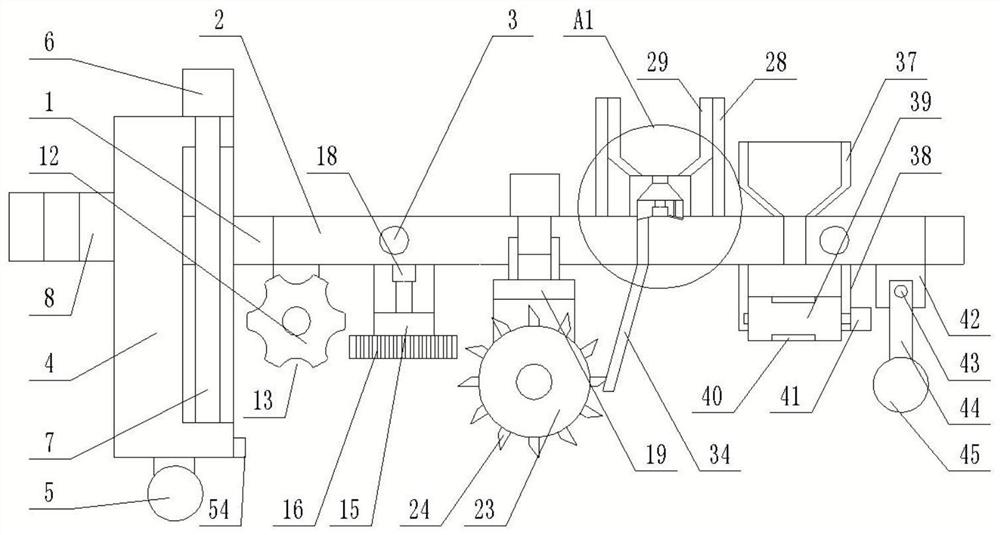
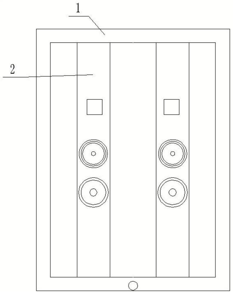
[0035] refer to Figure 1-7 , the present invention provides an intelligent seeding and fertilizing machine suitable for intercropping, comprising: a fixed frame 1, a plurality of sowing devices are arranged in parallel in the fixed frame 1, and the plurality of sowing devices are respectively used for sowing different seeds suitable for intercropping and sowing at alternate intervals ;
[0036] The sowing device includes a frame 2, a plurality of guide columns 3 are fixedly connected in the fixed frame 1, and the plurality of guide columns 3 run through the side of the frame 2, and the bottom surface of the frame 2 is respectively provided with a cutting mechanism, a cleaning mechanism, a ditching mechanism, and a fertilization mechanism. , sowing mechanism and soil covering mechanism; the end of the fixed frame 1 near the cutting mechanism is provided with a lifting plate 4, the bottom surface of the lifting plate 4 is fixedly connected with a number of guide wheels 5, and o...
Embodiment 2
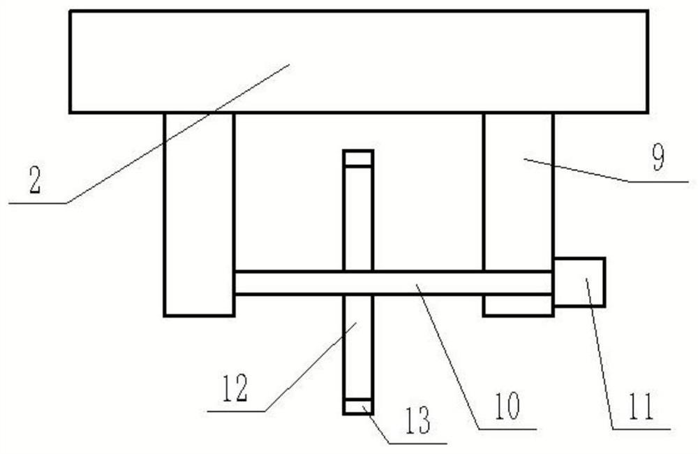
[0055] refer to Figure 8-9, because the most suitable row spacing for growth and development required by different types of crops is different, so this embodiment proposes a control mechanism. The two ends are fixedly connected with the two inner walls of the fixed frame 1 respectively, and the side of the frame 2 is provided with a distance-adjusting hole, the outer wall of the bearing 47 is fixed in the distance-adjusting hole, the inner wall of the bearing 47 is fixedly connected with a threaded cylinder 48, and the inner wall of the threaded cylinder 48 It is threadedly connected with the pitch-adjusting screw rod 46, and the outer wall of the threaded barrel 48 is fixedly connected with a driven gear 49, and the driven gear 49 is meshed with a driving gear 50. The side of the frame 2 is embedded with a pitch-adjusting motor 51, and the output end of the pitch-adjusting motor 51 is connected to the The driving gear 50 is fixedly connected. Such setting can carry out indi...
Embodiment 3
[0057] refer to Figure 10 , in the process of fertilization, it is usually necessary to mix and use a variety of chemical fertilizers to supply various nutrients to the crops. In order to save the process of manual stirring, this embodiment proposes a stirring mechanism. The stirring mechanism includes stirring Rod 52, the bottom surface of stirring rod 52 is affixed to the top surface of conical block 32, is that the top outer wall of stirring rod 52 is provided with several stirring struts 53, realizes the linkage that fertilizer is stirred simultaneously in the fertilizer grinding process.
PUM
 Abstract
Description
Claims
Application Information
 - Generate Ideas
- Intellectual Property
- Life Sciences
- Materials
- Tech Scout
- Unparalleled Data Quality
- Higher Quality Content
- 60% Fewer Hallucinations
Browse by: Latest US Patents, China's latest patents, Technical Efficacy Thesaurus, Application Domain, Technology Topic, Popular Technical Reports.
© 2025 PatSnap. All rights reserved.Legal|Privacy policy|Modern Slavery Act Transparency Statement|Sitemap|About US| Contact US: help@patsnap.com