Brake pad friction block pressing device and method

A technology of friction blocks and brake pads, which is applied in the field of brake pad pressing, can solve problems such as the friction block of brake pads falling off, and achieve the effects of avoiding fracture and falling off, weakening the arch bridge effect, and working stably and effectively

Pending Publication Date: 2022-01-21
BEIJING TIANYISHANGJIA NEW MATERIAL
View PDF0 Cites 0 Cited by
  • Summary
  • Abstract
  • Description
  • Claims
  • Application Information

AI Technical Summary

Problems solved by technology

[0004] Therefore, the technical problem to be solved by the present invention is to overcome the defects that the brake pad friction block in the prior art has many internal defects after being pressed and formed, which leads to the risk of the brake pad friction block falling off the steel back when the train brakes, thereby providing Device and method for pressing brake pad friction block

Method used


Image

  • Brake pad friction block pressing device and method
  • Brake pad friction block pressing device and method

Examples


Embodiment 1

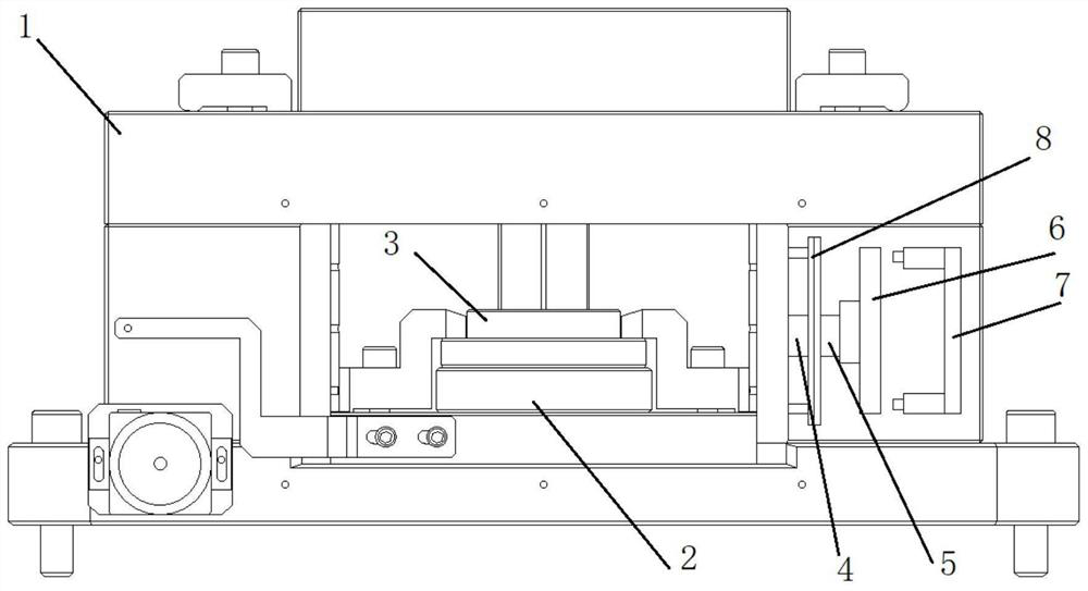
[0035] Such as figure 1 Shown is a brake pad friction block pressing device provided by this embodiment, including: a supporting cavity structure as the installation assembly 1, a stamping mechanism for pressing and forming, and a vibration mechanism for driving the stamping mechanism to vibrate. A pressing chamber is arranged in the mounting assembly 1, the stamping mechanism is installed in the pressing chamber, and the vibration mechanism is installed on the outer wall of the pressing chamber.

[0036] The stamping mechanism is installed on the mounting assembly 1. The stamping mechanism includes a stamping die 2 and a stamping head 3 arranged coaxially. The stamping die 2 is fixedly installed on the bottom of the pressing chamber, and the stamping head 3 is installed on the top of the pressing chamber through a cylinder. The cylinder drives the stamping The head 3 moves up and down to press or demould the materials in the stamping die 2 .

[0037] The vibrating mechanism ...

Embodiment 2

[0041] This embodiment provides a brake friction block pressing method, using the brake friction block pressing device provided in Example 1, including the following steps:

[0042] First, inject the powder material into the stamping die of the stamping mechanism, use the vibration mechanism to drive the stamping die to vibrate for 30s, the amplitude range is 1-2mm, and the vibration frequency is 40-60Hz; the vibration time, amplitude range and vibration frequency can be determined according to the metal in the powder The ratio of copper powder and graphite powder is adjusted. In this embodiment, the vibration frequency is 50 Hz, and the amplitude is 2 mm.

[0043] After the vibration is completed, the mold is closed to press the powder material. The cylinder drives the punching head down and extends into the punching die. When the punching head touches the material in a single step, it continues to descend for 5mm, and then maintains the pressing state for 3s. The rear cyli...


PUM


Abstract

The invention relates to the technical field of brake pad pressing, in particular to a brake pad friction block pressing device and method. The brake pad friction block pressing device comprises a mounting assembly, a stamping mechanism and a vibration mechanism. The stamping mechanism is mounted on the mounting assembly, and the stamping mechanism comprises a stamping die and a stamping head which are coaxially arranged. The vibration mechanism is provided with a first sliding part and a second sliding part which are in sliding connection, the first sliding part is fixedly installed on the mounting assembly, a first vibration part is installed at the end, away from the first sliding part, of the second sliding part in the sliding direction, a second vibration part is installed on the mounting assembly, and the first vibration part moves towards or away from the second vibration part under the action of the second vibration part. According to the brake pad friction block pressing device and method, internal cracks of a brake pad friction block obtained after vibrating pressing can be greatly reduced, in the long-term running process of a train, a brake pad can stably and effectively work, the risk that the brake pad friction block breaks and falls off is avoided, and the manpower maintenance and overhaul cost during the running period of the train can be greatly reduced.

Description

technical field [0001] The invention relates to the technical field of brake pad pressing, in particular to a brake pad friction block pressing device and method. Background technique [0002] At present, powder metallurgy brake pads are mainly made of copper and iron mixed-based friction materials, and the main processes are mixing, pressing, and sintering. Pressing is the second basic process of the powder metallurgy process, which is the process of compacting the metal powder into a compact with a certain shape, porosity and strength. [0003] In the powder metallurgy brake pad friction block pressing process in the prior art, the forming process mainly includes: cloth-pressing-forming-demolding. Because the friction block material contains graphite powder and copper powder, due to the large difference in wetting angle between graphite and copper, and the surface of metallurgical powder particles is irregular, there is friction between each other, resulting in loose accu...

Claims


Application Information

Patent Timeline
Patent Type & Authority Applications(China)
IPC IPC(8): B22F3/03B22F3/00
CPCB22F3/03B22F3/005
Inventor 张振威程景琳曹静武丁向莹魏东彬周键龙波马成龙
Owner BEIJING TIANYISHANGJIA NEW MATERIAL
Why Eureka
Try Eureka