Composite pumped storage system and operation method thereof

A pumped storage and composite technology, applied in the field of physical energy storage, can solve problems such as ecological environment damage, damage to civil engineering, system efficiency reduction, etc., achieve efficient and stable operation, high-efficiency variable working conditions, and avoid environmental pollution.

Pending Publication Date: 2022-01-21
XI AN JIAOTONG UNIV
View PDF0 Cites 0 Cited by
  • Summary
  • Abstract
  • Description
  • Claims
  • Application Information

AI Technical Summary

Problems solved by technology

Although pumped storage systems have many advantages over other energy storage systems, pumped storage systems still have unavoidable disadvantages: pumped storage systems require an open-air environment, destroy civil engineering, build upper and lower reservoirs, and cause damage to the ecological environment
Changes in the liquid level in the underground roadway lead to changes in the liquid level difference between the upper and lower reservoirs, the water head height of the turbine changes, and the turbine deviates from the design working point to be in a variable working condition, which eventually leads to a decrease in system efficiency

Method used


Image

  • Composite pumped storage system and operation method thereof
  • Composite pumped storage system and operation method thereof
  • Composite pumped storage system and operation method thereof

Examples


Embodiment Construction

[0035] Below in conjunction with specific example the present invention is described in further detail:

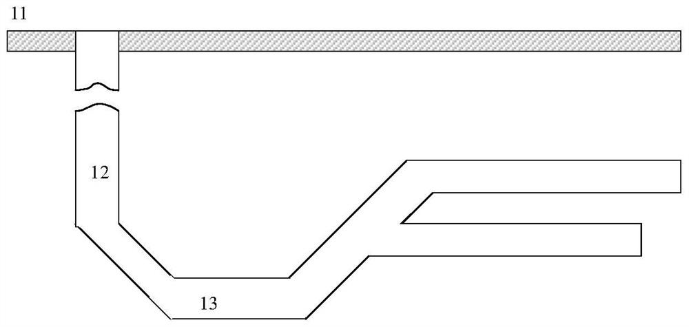
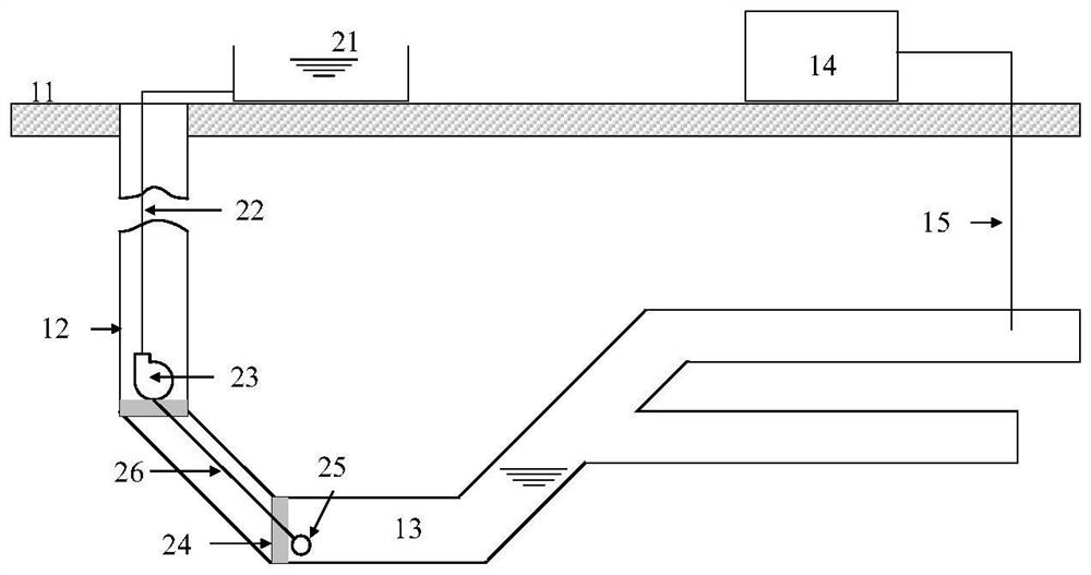
[0036] combine figure 1 , a schematic diagram of a coal mine structure used by a composite pumped storage system. The basic structure includes a ground 11, a coal mine shaft 12 and a coal mine roadway 13; the coal mine roadway 13 varies in altitude.

[0037] combine figure 2 , a composite pumped storage system includes a pumped storage module and a pressure regulation storage module 14 for adjusting the back pressure of the pump and turbine; the pumped storage module is composed of a ground reservoir 21 to form an upper reservoir, and a sluice wall 24 The sealed coal mine roadway 13 forms a lower reservoir, and an upper pipeline 22, a water pump turbine 23, a lower pipeline 26 and a filter 25 are arranged between the upper reservoir and the lower reservoir to connect in sequence; the connection point between the pressure regulating energy storage module 14 and the lower ...


PUM


Abstract

The invention discloses a composite pumped storage system and an operation method thereof. The system comprises a pumped storage module and a pressure regulating energy storage module; The pumped storage module comprises an upper reservoir and a lower reservoir which are communicated with each other, a ground reservoir forms the upper reservoir, a coal mine tunnel sealed by a sluice wall forms the lower reservoir, and a pump turbine and a filter are arranged between the upper reservoir and the lower reservoir; the pressure regulating and energy storing module comprises a compressor unit and an expansion unit, a low-pressure-stage compressor and a high-pressure-stage compressor are arranged in the compressor unit, a heat accumulator is arranged at an outlet of the compressor to utilize compression heat, and a fluidized bed reactor is installed in front of an inlet of the expansion unit to treat coal bed gas; inlets of all stages of expansion machines except a high-pressure-stage expansion machine are connected to an upper end outlet of the fluidized bed reactor through a tee joint and a control valve to deal with the problem of variable working conditions; and the back pressure of the pump turbine of the pumped storage module is constant, and the cavitation problem caused by the too low back pressure of the pump turbine set and the efficiency reduction caused by the too high back pressure are avoided.

Description

technical field [0001] The invention belongs to the fields of general equipment manufacturing and physical energy storage, and specifically relates to a composite pumped storage system and an operating method thereof. Background technique [0002] At present, there are many types of energy storage technologies, and among many physical energy storage technologies, only compressed air energy storage (CAES) and pumped hydro energy storage (PHES) can be applied on a large scale. Although pumped storage systems have many advantages over other energy storage systems, pumped storage systems still have unavoidable disadvantages: pumped storage systems require an open-air environment, destroy civil engineering, build upper and lower reservoirs, and cause damage to the ecological environment. [0003] Under the guidance of the concept of green and low-carbon development, many coal mines have been shut down across the country. In addition to the coal mines that have been mined, there a...

Claims


Application Information

Patent Timeline
IPC IPC(8): F03B13/06F04B41/06F01D13/02B01D29/11
CPCF03B13/06F04B41/06F01D13/02B01D29/11Y02E10/20Y02E60/16
Inventor 王焕然葛刚强孙昊贺新陶瑞黄一洲
Owner XI AN JIAOTONG UNIV
Why Eureka
Try Eureka