Optical imaging array system, near-eye display device and image projection method

An optical imaging and array technology, which is applied in the field of optical imaging array systems, can solve the problems of poor comfort, difficulty in viewing, and low imaging brightness, and achieve the effects of reduced size, light and compact structure, and improved comfort

Pending Publication Date: 2022-01-21
北京意链科技有限公司
View PDF0 Cites 0 Cited by
  • Summary
  • Abstract
  • Description
  • Claims
  • Application Information

AI Technical Summary

Problems solved by technology

However, at this time, there is also the problem that it is difficult to balance the clarity and brightness of the imaging.
Under the near-eye display, in order to reduce the aperture formed by the image light on the retina to the limit of human eye recognition, so that it is infinitely close to a point, it

Method used


Image

  • Optical imaging array system, near-eye display device and image projection method
  • Optical imaging array system, near-eye display device and image projection method
  • Optical imaging array system, near-eye display device and image projection method

Examples


Embodiment Construction

[0063] The application will be further described in detail below in conjunction with the accompanying drawings and embodiments. It should be understood that the specific embodiments described here are only used to explain related inventions, not to limit the invention. It should also be noted that, for ease of description, only parts related to the invention are shown in the drawings.

[0064] It should be noted that, in the case of no conflict, the embodiments in the present application and the features in the embodiments can be combined with each other. The present application will be described in detail below with reference to the accompanying drawings and embodiments.

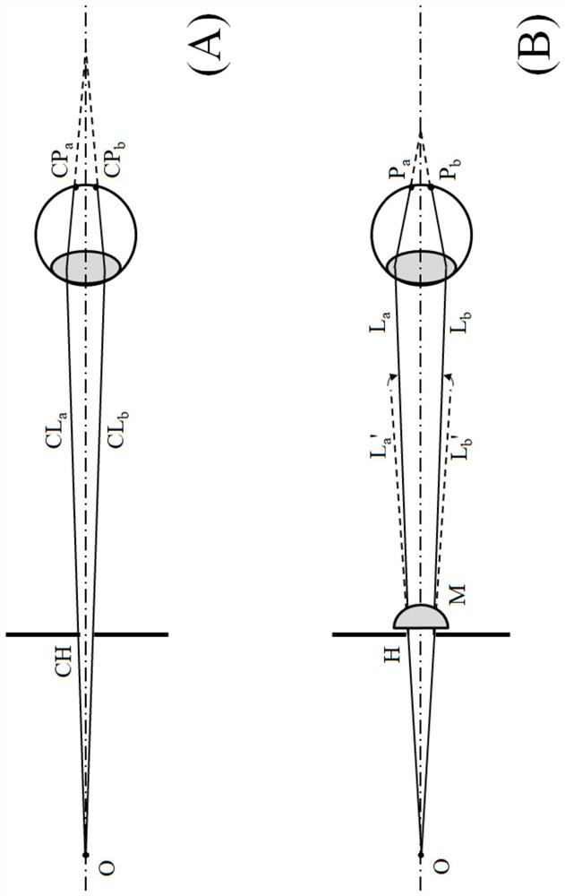
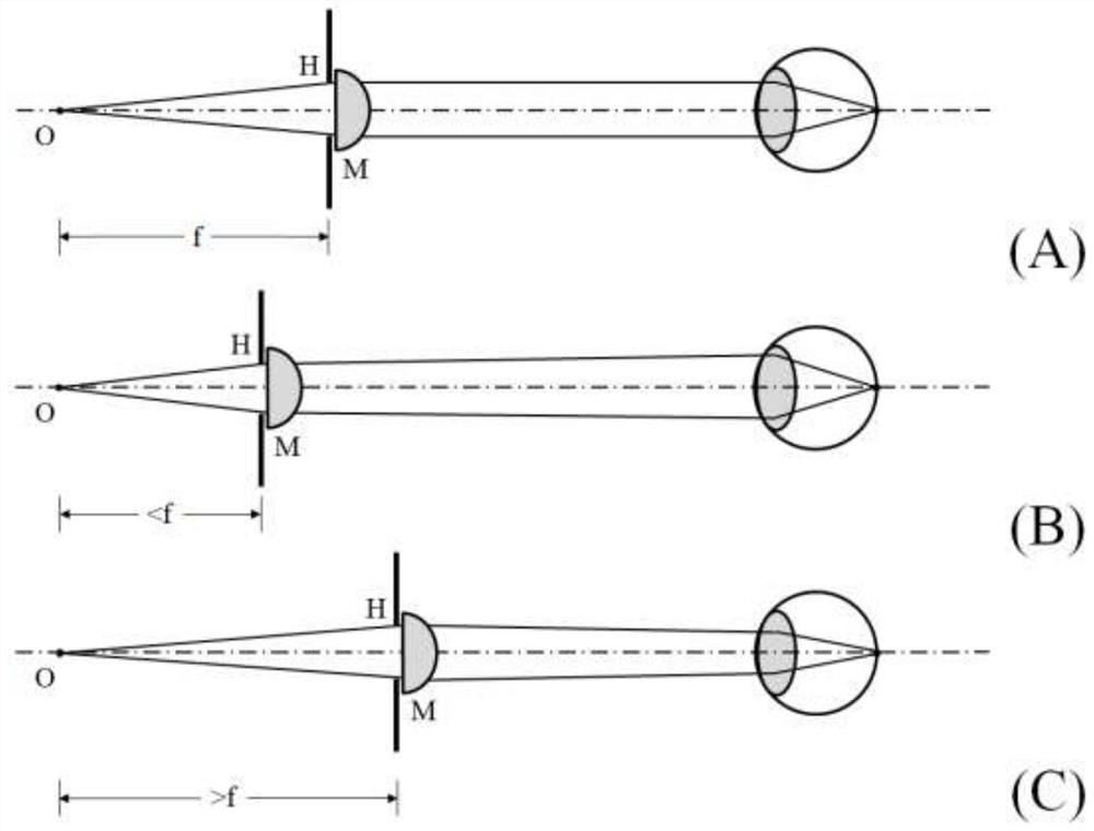
[0065] In the present application, for viewing an object under near-eye display, microlenses are provided adjacent to the small holes while improving the imaging clarity by using the small holes. There are many advantages to using the pinhole + microlens combination according to this application:

[0066...


PUM


Abstract

The invention discloses an optical imaging array system, and the system comprises: a micro-display array which comprises a circular micro-display and at least one group of annularly-arranged micro-displays located at the periphery of the micro-display; a small hole array and a micro-lens array which are located on the downstream of the micro-display array in the image light propagation direction and are adjacently arranged, wherein corresponding to the micro-display array, the small hole array comprises a small hole located in the center and at least one group of small holes which are annularly arranged, the micro-lens array comprises a micro-lens located in the center and at least one group of annularly arranged micro-lenses, and the number of the small holes and the number of the micro-lenses are the same as the number of the micro-displays, the micro-displays, the small holes and the micro-lenses are in one-to-one correspondence to form corresponding light channels, wherein in each light channel, image light emitted by the micro-displays is shielded by the small holes and modulated by the micro-lenses and then enters pupils and forms an image in a preset area of the retina, and a round view field is integrally formed; the application comfort can be improved due to the natural state close to the visual field of human eyes.

Description

technical field [0001] The present application generally relates to the field of optical display, and in particular to an optical imaging array system with a circular field of view, a near-eye display device and an image projection method. Background technique [0002] With the development of computer technology and display technology, virtual reality (Virtual Reality, VR) technology to experience the virtual world through computer simulation system, and augmented reality (Augmented Reality, AR) technology and hybrid technology to integrate display content into real environment background. Reality (Mixed Reality, MR) technology has developed rapidly. [0003] Near-eye VR, AR and MR display technologies that combine VR, AR and MR technologies with near-eye displays are important new display technologies that can bring unprecedented visual experience and human-computer interaction. Near-eye VR display technology mainly pursues immersive virtual display with large field of vie...

Claims


Application Information

Patent Timeline
IPC IPC(8): G02B27/01G02B30/27
CPCG02B27/0101G02B30/27
Inventor 盛大成黄正宇
Owner 北京意链科技有限公司
Why Eureka
Try Eureka