
Medicine sampling device for medicine analysis

A sampling device and drug technology, applied in the direction of sampling device, sampling, measuring device, etc., can solve the problems of slow dissolution rate of solid drugs, time-consuming and labor-intensive operation, non-use, etc., so as to facilitate re-use, improve crushing efficiency, and facilitate cleaning and drying effect

Pending Publication Date: 2022-01-25
李洪臣
View PDF1 Cites 0 Cited by
  • Summary
  • Abstract
  • Description
  • Claims
  • Application Information

AI Technical Summary

Problems solved by technology

[0004] The drug sampling device in the prior art still has the following disadvantages in actual use: the existing device generally samples the liquid drug, and does not use it for sampling the solid drug, and the solid drug needs to be dissolved in a solvent to form a drug solution , this process is currently mostly artificially crushing the drug, and then adding a solvent to stir and dissolve it to make a liquid drug. The operation is very time-consuming and laborious, and the dissolution rate of the solid drug is also slow. Therefore, the present invention proposes a drug sampling device for drug analysis.

Method used


Image

  • Medicine sampling device for medicine analysis
  • Medicine sampling device for medicine analysis
  • Medicine sampling device for medicine analysis

Examples


Embodiment 1

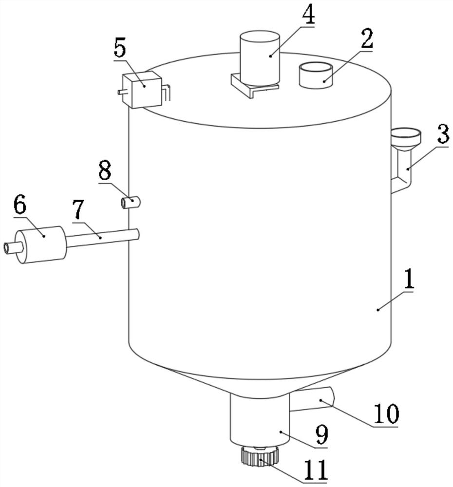
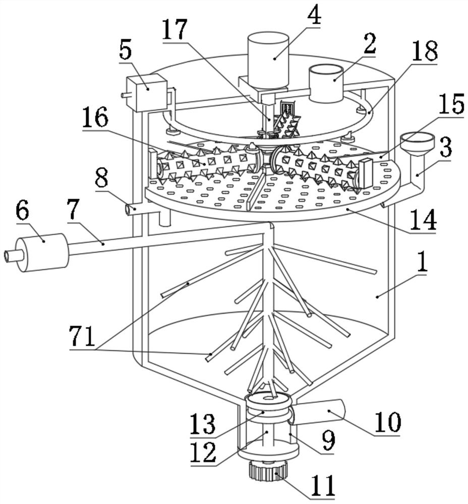
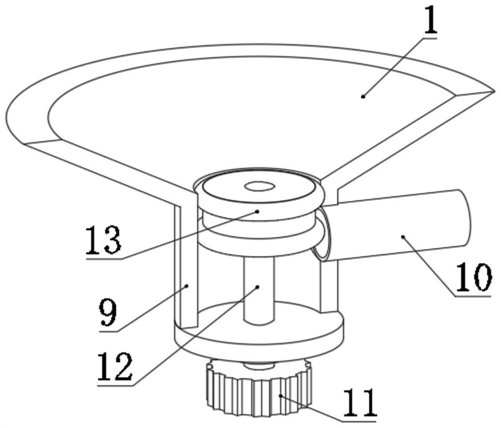
[0046] refer to Figure 1-9 , a drug sampling device for drug analysis, comprising a tank body 1, a delivery tube 2 is installed on the top of the tank body 1, and solid drugs are dropped into the tank body 1 through the delivery tube 2. The bottom of the tank body 1 is bucket-shaped and is equipped with a piston tube 9, a liquid discharge tube 10 is installed on one side of the upper end of the piston tube 9, and a piston mechanism is arranged inside the piston tube 9;

[0047] The piston mechanism includes a piston 13 slidably arranged inside the piston tube 9 , and a rubber sealing ring is fixedly installed on the outside of the piston 13 . The height of the piston 13 is less than the distance between the lower edge of the drain pipe 10 and the inner bottom wall of the piston tube 9, and the vertical thread in the middle of the piston 13 is equipped with a screw rod 12, and the bottom end of the screw rod 12 extends to the bottom of the piston tube 9. The lower side is equip...

Embodiment 2

[0063] refer to Figure 10-12 In this second embodiment, on the basis of the first embodiment above, a heating mechanism 22 is installed on the aeration pipe 7. The heating mechanism 22 includes a heating pipe 221 communicated with the aeration pipe 7, and the heating pipe 221 is fixed on the aeration pipe 7. , and the heating pipe 221 is located outside the tank body 1, and a heating wire 222 is installed in the heating pipe 221.

[0064] After the device is cleaned, the aeration mechanism continues to deliver the airflow into the tank body 1, and cooperates with the heating of the heating wire 222, so that the temperature of the airflow flowing through the heating pipe 221 is increased to form a hot airflow, and the hot airflow enters the inside of the tank body 1. Water stains inside dry quickly. The air flow is finally discharged from the exhaust pipe 8 . Through the rapid drying of the tank body 1, it is convenient for the device to be put into use quickly again.


PUM


Abstract

The invention discloses a medicine sampling device for medicine analysis, and belongs to the field of medicine sampling. The medicine sampling device comprises a tank body, the top of the tank body is provided with a feeding pipe, the bottom of the tank body is bucket-shaped and is provided with a piston pipe, one side of the upper end of the piston pipe is provided with a liquid discharge pipe, and the piston pipe is internally provided with a piston mechanism; a motor is mounted at the top of the tank body, a mesh plate is rotatably mounted in the tank body, a plurality of cleaning strips are fixed on the inner wall of the tank body, the bottom walls of the cleaning strips are in friction contact with the top surface of the mesh plate, and a solvent pipe is mounted on the outer side of the tank body. Solid medicine is rapidly and efficiently crushed through the crushing mechanism to form powder, then the medicine powder and a solvent are fully mixed through the aeration mechanism to be dissolved to form medicine liquid, and the medicine liquid can be used for analysis and detection after being taken out; and the device can be conveniently cleaned and dried when used and can be conveniently put into use again.

Description

technical field [0001] The invention relates to the technical field of medicine sampling, in particular to a medicine sampling device for medicine analysis. Background technique [0002] Sampling refers to the process of extracting individuals or samples from the population, that is, the process of testing or observing the population. There are two types of random sampling and non-random sampling. The former refers to the sampling method of drawing samples from the population according to the principle of randomization. [0003] After retrieval, Chinese Patent No. CN 213022435 U discloses a liquid medicine sampling device for drug analysis, including a device main body, four legs are fixedly welded at the bottom of the device main body, and a door is fixedly installed on the front end of the device main body Shaft, the outer side of the door shaft is movably installed with a bin door, the top of the main body of the device is fixed with a mixing chamber, the inside of the ma...

Claims


Application Information

Patent Timeline
IPC IPC(8): G01N1/14G01N1/28G01N1/38
CPCG01N1/14G01N1/286G01N1/38
Inventor 李洪臣
Owner 李洪臣
Learn More