Backflow type sewage treatment reactor based on catalytic reaction mechanism

A technology for sewage treatment and catalytic reaction, which is used in oxidized water/sewage treatment, water/sewage treatment, special compound water treatment, etc. It can solve the problems of difficult to ensure the dissolved oxygen content of sewage, low stirring efficiency, and few hydroxyl radical substances. , to increase the effect of sewage treatment, improve the stirring efficiency, and increase the contact area.

Active Publication Date: 2022-01-28
ANYANG INST OF TECH
View PDF4 Cites 0 Cited by
  • Summary
  • Abstract
  • Description
  • Claims
  • Application Information

AI Technical Summary

Problems solved by technology

[0004] The object of the present invention is to provide a kind of reflux type sewage treatment reactor based on catalytic reaction mechanism, through reaction tank, reflux driving mechanism, rotary catalytic component, force component, reflux warmer, reflux pipe, heat transfer component, supply The design of the heater, the reflux component and the propeller solves the problem that most of the existing sewage catalytic reaction devices use a stirrer or a stirrer for stirring, which not only has low stirring efficiency and poor stirring effect, but also is difficult to ensure a certain amount of dissolved oxygen in the sewage. The amount of hydroxyl radicals produced is less, thereby reducing the sewage treatment effect, which is not convenient for the recovery of the heterogeneous catalyst after the reaction, and the heating uniformity of the reaction solution is low, which leads to the problem of poor sewage treatment effect

Method used


Image

  • Backflow type sewage treatment reactor based on catalytic reaction mechanism
  • Backflow type sewage treatment reactor based on catalytic reaction mechanism
  • Backflow type sewage treatment reactor based on catalytic reaction mechanism

Examples


Embodiment Construction

[0041] The following will clearly and completely describe the technical solutions in the embodiments of the present invention with reference to the accompanying drawings in the embodiments of the present invention. Obviously, the described embodiments are only some, not all, embodiments of the present invention. Based on the embodiments of the present invention, all other embodiments obtained by persons of ordinary skill in the art without creative efforts fall within the protection scope of the present invention.

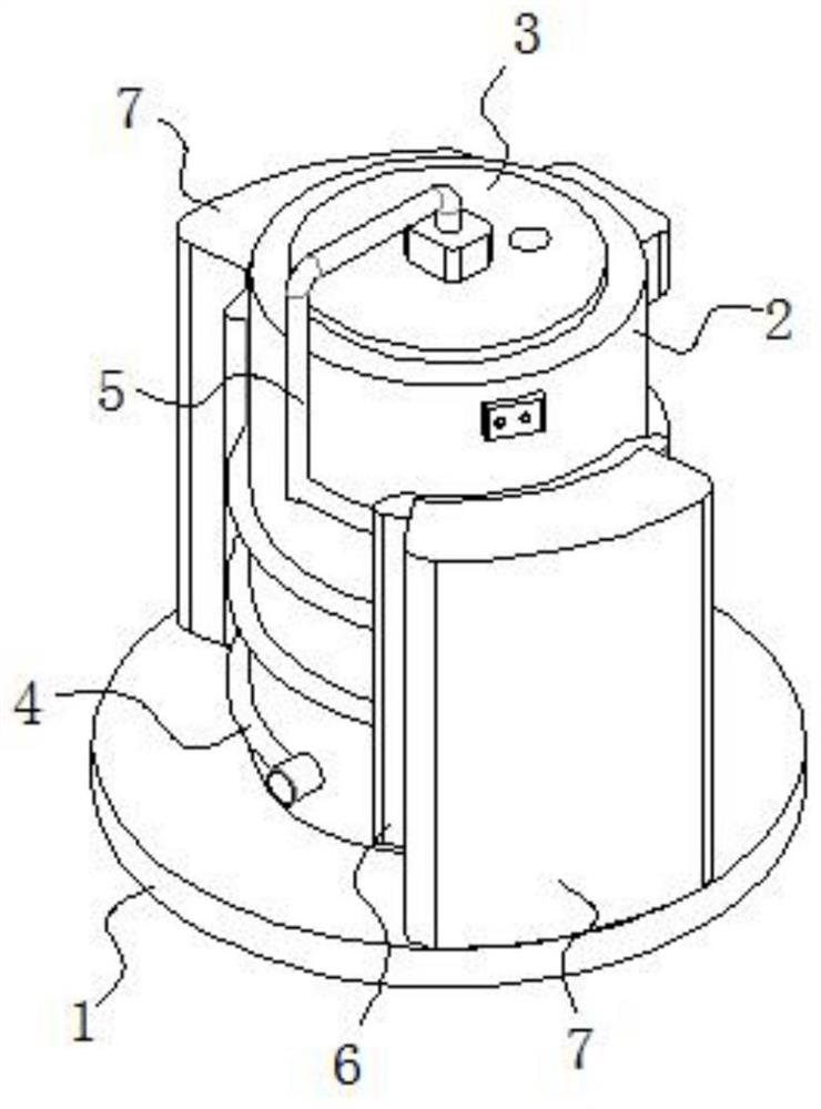
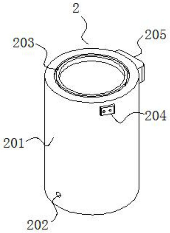
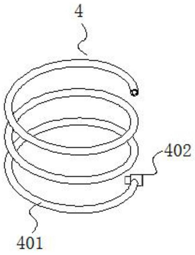
[0042] see Figure 1-15 , the present invention is a kind of reflux type sewage treatment reactor based on catalytic reaction mechanism, comprises base 1; Reaction tank 2 is fixed on the upper surface of base 1, and the inside of reaction tank 2 is provided with the rotating catalytic device 3 that cooperates with its rotation; Reaction The outside of the tank 2 is connected with a reflux heater 4 sleeved on the reaction tank 2, and the upper end of the reflux heat...


PUM


Abstract

The invention discloses a backflow type sewage treatment reactor based on a catalytic reaction mechanism, and relates to the technical field of sewage treatment. The backflow type sewage treatment reactor comprises a base, wherein a reaction tank is fixed on the upper surface of the base, a rotary catalysis device rotationally matched with the reaction tank is arranged in the reaction tank, the outer portion of the reaction tank is communicated and connected with a backflow warmer sleeved on the reaction tank, a backflow pipe connected with the rotary catalysis device is fixed at the upper end portion of the backflow warmer, two heat transfer assemblies are symmetrically arranged on the upper surface of the base, the backflow warmer is in clearance fit with the heat transfer assemblies, and two heat supply devices are symmetrically arranged on the upper surface of the base and attached to the heat transfer assemblies. According to the present invention, with the design of the backflow warmer, the backflow pipe, the supercharger, the backflow assembly, the heat transfer assembly and the heat supply device, the heating of the sewage in the backflow warmer can be achieved, and the backflow type heating of the sewage in the reaction tank is achieved through the loop formed by the reaction tank, the backflow warmer, the backflow pipe and the backflow assembly, so that the sewage heating uniformity is substantially improved.

Description

technical field [0001] The invention belongs to the technical field of sewage treatment, in particular to a reflux sewage treatment reactor based on a catalytic reaction mechanism. Background technique [0002] As we all know, heterogeneous catalytic oxidation technology is to use carbon-based catalysts loaded with special components to fill, and at the same time pass water to aerate to form a three-phase contact fluidized bed system to ensure that dissolved oxygen in water can produce catalytic reactions on the catalyst surface in a larger area. Produce hydroxyl radical substances for oxidative decomposition of organic pollutants. [0003] However, the inventors of the present application found that the sewage catalytic reaction device in the prior art still has the following deficiencies during the implementation of the specific embodiments of the present invention: (1) most of the existing sewage catalytic reaction devices use stirring bars or stirring Stirring with a ro...

Claims


Application Information

Patent Timeline
Patent Type & Authority Applications(China)
IPC IPC(8): C02F1/72
CPCC02F1/725C02F2201/002C02F2301/02C02F2305/023Y02W10/10
Inventor 刘超贺琼陈彦涛田大勇牛永生
Owner ANYANG INST OF TECH
Why Eureka
Try Eureka