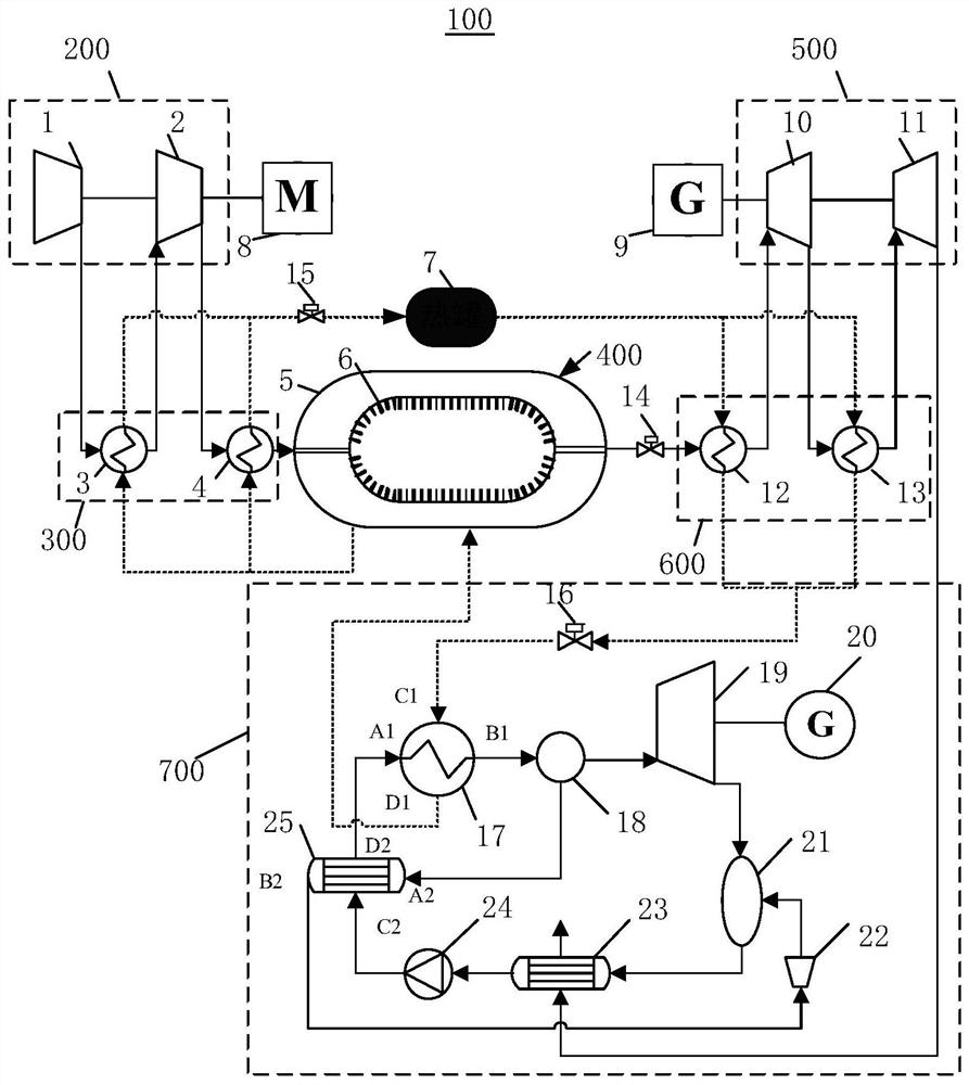
Compressed air energy storage system coupled with Kalina cycle

A compressed air energy storage and Karina cycle technology, applied in the field of energy storage, can solve the problems of reduced system operation efficiency, rising temperature of heat storage medium, waste of heat energy, etc., to reduce heat loss, increase energy storage capacity, and improve storage capacity. The effect of energy efficiency

Active Publication Date: 2022-01-28
QINGHAI UNIVERSITY +1
View PDF4 Cites 2 Cited by
  • Summary
  • Abstract
  • Description
  • Claims
  • Application Information

AI Technical Summary

Problems solved by technology

[0004] However, the existing advanced adiabatic compressed air energy storage (AA-CAES) system will generate a large amount of compression heat during operation, which cannot be completely transferred to the energy release process due to the limitation of the heat transfer temperature difference of the heat exchanger. Compressed air, so the heat of the system cannot be fully utilized, reducing the operating efficiency of the system, and at the same time, it will cause the temperature of the heat storage medium in the heat storage system to rise, which will have an adverse effect on the next operation of the system. The solution is usually to introduce additional cooling device, but this will lead to an increase in system complexity and waste of heat

Method used


Image

  • Compressed air energy storage system coupled with Kalina cycle
  • Compressed air energy storage system coupled with Kalina cycle

Examples


Embodiment Construction

[0026] In order to make the purpose, technical solutions and advantages of the embodiments of the present invention clearer, the technical solutions in the embodiments of the present invention will be clearly and completely described below in conjunction with the drawings in the embodiments of the present invention. Obviously, the described embodiments It is a part of embodiments of the present invention, but not all embodiments. The components of the embodiments of the invention generally described and illustrated in the figures herein may be arranged and designed in a variety of different configurations.

[0027] Accordingly, the following detailed description of the embodiments of the invention provided in the accompanying drawings is not intended to limit the scope of the claimed invention, but merely represents selected embodiments of the invention. Based on the embodiments of the present invention, all other embodiments obtained by persons of ordinary skill in the art wi...


PUM


Abstract

The invention provides a compressed air energy storage system coupled with Kalina cycle, and belongs to the technical field of energy storage. The system comprises a double-layer storage tank and a Kalina cycle unit. The double-layer storage tank, a multi-stage cooler, a heat storage tank, a multi-stage heat regenerator, a C1 port and a D1 port are sequentially communicated to form a circulation loop, and an internal flowing medium is heat conduction oil; the heat conduction oil is heated by compressed air and then stored in the heat storage tank; the heat conduction oil heats the compressed air flowing through the multi-stage heat regenerator; and the heat conduction oil heats an ammonia water solution flowing through an evaporator by utilizing residual heat and flows back to the double-layer storage tank. A port B1, a separator, an ammonia expansion machine, an absorber, a condenser, a working medium pump, a port C2, a port D2 and a port A1 are sequentially communicated to form a circulation loop, an internal flowing medium is an ammonia water solution; and the ammonia expansion machine is used for expanding ammonia-rich steam from the separator to do work and pushing a second power generator to output electric power. Therefore, the energy storage capacity of the system can be effectively increased, heat loss in the energy storage process is reduced, and the energy storage efficiency is improved.

Description

technical field [0001] The invention relates to the technical field of energy storage, in particular to a compressed air energy storage system coupled with a Karina cycle. Background technique [0002] With the vigorous development of renewable energy, distributed energy supply and smart grid in China, the capacity of the grid continues to expand, and the peak-to-valley difference in power consumption is increasing, and the demand for energy storage technology is increasing. The large-scale development of energy storage technology can effectively solve the problem of unstable power generation of intermittent renewable energy such as wind energy and solar energy, smooth fluctuating power input, realize peak-shaving and valley-filling of the power grid, improve the utilization rate of renewable energy power generation, and enhance power grid operation security. [0003] Among the existing large-scale electric energy storage technologies, compressed air energy storage has been...

Claims


Application Information

Patent Timeline
Patent Type & Authority Applications(China)
IPC IPC(8): F01K7/02F01K13/00F01K13/02F01K17/02F01K21/00F01K27/00
CPCF01K7/02F01K27/00F01K17/02F01K21/00F01K13/00F01K13/02F01K13/006Y02E70/30
Inventor 郑天文陈来军梅生伟张跃司杨郭永庆陈晓弢
Owner QINGHAI UNIVERSITY
Why Eureka
Try Eureka