
Intravascular stent

A vascular stent and blood flow technology, applied in the field of vascular stents, can solve problems such as the inability to provide vascular stents, reduce extrusion resistance, increase vascular stents, etc., and achieve the effects of increasing flexibility, ensuring strength, and ensuring flexibility.

Pending Publication Date: 2022-02-08
SHANGHAI MICROPORT MEDICAL (GROUP) CO LTD
View PDF0 Cites 1 Cited by
  • Summary
  • Abstract
  • Description
  • Claims
  • Application Information

AI Technical Summary

Problems solved by technology

[0004] In response to the above problems, two technical routes are currently adopted, one is to reduce the wall thickness of the vascular stent, but there are certain defects in the overall thinning of the wall thickness of the vascular stent, and the thinning of the wall thickness will lead to a decrease in extrusion resistance. Vascular stents cannot provide enough supporting force to prop up the lesion. In addition, as the wall thickness becomes thinner, the vascular stent becomes more fragile as a whole, and it is easy to twist and deform when encountering calcified lesions
The other is to adjust the overall structure of the vascular stent, such as adjusting the length of the vascular stent, the number of support rings, the number of connecting rods, etc., to improve the intravascular hydrodynamic environment by changing the flexibility of the vascular stent, but blood flows through the blood vessel There is still vortex generation during stenting, which usually increases the risk of in-stent restenosis

Method used


Image

  • Intravascular stent
  • Intravascular stent
  • Intravascular stent

Examples


Embodiment 1

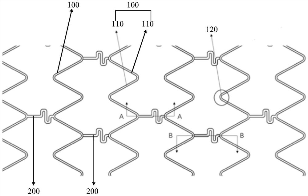
[0059] Such as Figure 1 to Figure 3 As shown, the present embodiment provides a medium vascular stent, the vascular stent includes a plurality of support rings 100 and a plurality of connecting rods 200; The adjoining regions 120 of two adjacent support rods 110 are connected. Wherein, the supporting ring 100 is formed by connecting a plurality of supporting rods 110 connected end to end, and the wall thickness D1 of the supporting rods 110 is 0.1 mm. A part of the connecting rod 200 has a groove 210 on the side wall near the central axis of the vascular stent, and the distance D2 between the bottom of the groove 210 and the side wall of the connecting rod 200 away from the central axis of the vascular stent (that is, the wall of the connecting rod 200 Thickness) is 0.05m, the groove 210 does not exceed any side surface of the connecting rod 200 range, the groove wall of the groove 210 forms a smooth transition zone 220 corresponding to the blood flow direction, the notch of...

Embodiment 2

[0061] Such as Figure 4 , Figure 5 As shown, the present embodiment provides a vascular stent, which includes a plurality of support rings 100 and a plurality of connecting rods 200; the support rings 100 are distributed at intervals along the central axis of the vascular stent. Wherein, the supporting ring 100 is formed by connecting a plurality of supporting rods 110 connected end to end, and the wall thickness D1 of the supporting rods 110 is 0.1 mm. One end of the connecting rod 200 is connected to the adjoining regions 120 of two adjacent support rods 110, and the other end of the connecting rod 200 is connected to the adjoining regions 120 of two adjacent supporting rods 110 through a reinforcing part 300, and the reinforcing part 300 The shape is an "S" placed horizontally. There is a groove 210 on the side wall of the connecting rod 200 away from the central axis of the vascular stent, and the distance D2 between the bottom of the groove 210 and the side wall of th...

Embodiment 3

[0063] Such as Figure 5 As shown, the present embodiment provides a vascular stent, which includes a plurality of support rings 100 and a plurality of connecting rods 200; the support rings 100 are distributed at intervals along the central axis of the vascular stent. Wherein, the support ring 100 is formed by connecting a plurality of support rods 110 connected end to end, and the wall thickness D1 of the support rods 110 is 0.1mm; . A groove 210 is provided on the two side walls of the connecting rod 200 away from and close to the central axis of the vascular stent, and the two grooves 210 are aligned and distributed, and the distance D2 between the groove bottoms (ie, the wall thickness of the connecting rod 200) is 0.05mm The groove 210 does not exceed any side surface of the entire connecting rod 200 to form a concave area, and the groove wall of the groove 210 forms a smooth transition zone 220 corresponding to the direction of blood flow. The notch of the groove 210 i...


PUM


Abstract

The invention relates to an intravascular stent. The intravascular stent comprises a plurality of supporting rings and a plurality of connecting rods, wherein the supporting rings are distributed at intervals in the length direction of the intravascular stent, the connecting rods are arranged between and connected with every two corresponding adjacent supporting rings, and the wall thickness of at least one part of the connecting rods is smaller than the wall thickness of the supporting rings. According to the intravascular stent, the design of different wall thicknesses can be carried out in a specified position area, and the detail structure of the intravascular stent is adjusted to achieve the effect that the intravascular stent has different wall thicknesses, so the flexibility of a thinned position (namely a connecting rod) can be ensured, the generation of a low-shear-stress area is reduced, vortex generation probability is reduced, a secondary stenosis rate is reduced, the strength of other positions (namely the supporting rings) with the non-thinned walls is ensured, and the whole intravascular stent still keeps good supporting performance.

Description

technical field [0001] The invention relates to the technical field of medical instruments, in particular to a blood vessel stent. Background technique [0002] Atherosclerosis is currently considered to be a chronic inflammatory disease that starts at a young age and lasts for decades, and clinical symptoms of atherosclerosis usually appear in adulthood. The basic pathological change is the formation of plaques on the intima of the arteries, including lipid streaks, fibrous plaques, and atheromatous plaques, which can cause vascular lumen stenosis or thrombosis. Among them, the interventional medical treatment of vascular stents has become the main treatment method for such vascular diseases. [0003] However, many studies have shown that after the stent is implanted, the blood flow mode near the stent will change when the blood flows through it, and the fluid environment plays an important role in the repair of the damaged intima of the blood vessel and the generation of ...

Claims


Application Information

Patent Timeline
Patent Type & Authority Applications(China)
IPC IPC(8): A61F2/915
CPCA61F2/915A61F2002/91575A61F2002/91541
Inventor 李杰常兆华
Owner SHANGHAI MICROPORT MEDICAL (GROUP) CO LTD
Learn More