Tundish nozzle steel retaining groove, tundish nozzle and preparation method

A tundish and steel trough technology, applied in the field of tundish nozzle retaining grooves, can solve problems such as clogging of tundish nozzles, failure to start pouring, low tundish baking temperature and molten steel temperature, etc., so as to extend the flow path and avoid nozzles. The effect of too fast erosion

Pending Publication Date: 2022-02-08
北京利尔高温材料股份有限公司
View PDF1 Cites 0 Cited by
  • Summary
  • Abstract
  • Description
  • Claims
  • Application Information

AI Technical Summary

Problems solved by technology

[0003] The tundish first receives the molten steel poured from the ladle, and then distributes it to each crystallizer from the tundish nozzle at the bottom. At present, the tundish still has the following problems during the steel pouring process of the continuous casting machine: 1. Ladle steel The water flows into the tundish through the long nozzle and then flows into each tundish nozzle after being diverted. Often, the tundish has a low online baking temperature or a low temperature of the molten steel in the ladle, causing the molten steel to freeze at the tundish nozzle, resulting in failure of pouring ;2. Due to the large-sized inclusions in the tundish collecting at the nozzle of the tundish, the nozzle of the tundish is blocked; 3. The molten steel forms a vortex at the nozzle of the tundish, which accelerates the erosion of the nozzle by the molten steel, causing the tundish to be off the assembly line in advance; 4. For multi-flow tundishes, the distance from molten steel to each nozzle is different. For the short-distance molten steel flow, its flow path should be extended as much as possible so that the inclusions in molten steel have enough time to float to the surface of molten steel and thus Adsorbed by covering agent
The patent with the publication number CN203371034U discloses a slag-retaining device for the nozzle of the tundish. During the process, the residual steel slag on the tundish cover was heated and fell off into the water inlet. At the same time, the problem of slag rolling in the nozzle was avoided at the initial stage of pouring, but the above problems still could not be solved.

Method used


Image

  • Tundish nozzle steel retaining groove, tundish nozzle and preparation method
  • Tundish nozzle steel retaining groove, tundish nozzle and preparation method
  • Tundish nozzle steel retaining groove, tundish nozzle and preparation method

Examples


Embodiment 1

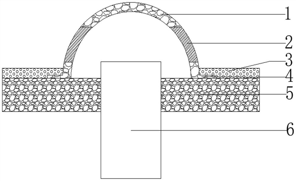
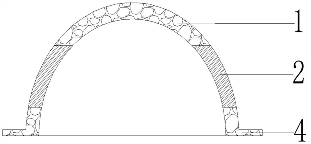
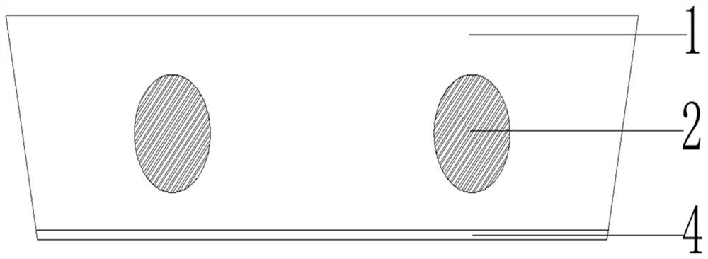
[0044] Such as figure 1 , 2 , 3, and 4, the tundish nozzle retaining steel channel described in this embodiment includes a steel retaining channel main body 1 and a blocking steel plate 2 .

[0045] The main body 1 of the retaining steel channel is an inverted groove structure with a circular arc in cross section. The two ends of the main body 1 of the retaining steel channel are closed. Fitted and connected with the working lining 5 at the bottom of the tundish; 4 (2 pairs) diversion holes are arranged on the arc side wall of the main body 1 of the retaining steel channel, and each pair of diversion holes is symmetrically arranged, and the symmetrical plane is the retaining steel channel The axis of the main body is perpendicular to the plane of the bottom working lining of the tundish, and the height of the bottommost ends of the four diversion holes is higher than the height of the working lining of the tundish bottom;

[0046] The blocking steel plate 2 is arranged in th...

Embodiment 2

[0054] The tundish nozzle described in this embodiment includes the tundish nozzle main body 6 and the tundish nozzle retaining steel channel, the structure of the tundish nozzle retaining steel channel is the same as that in Embodiment 1, and the tundish nozzle retaining steel channel is arranged on the tundish nozzle main body 6, the anti-floating outer edge 4 of the bottom edge of the tundish nozzle retaining steel channel fits with the working lining of the tundish bottom, and works with the tundish bottom through the fixed refractory material 3 arranged on the anti-floating outer edge 4 Lining 5 is connected.

Embodiment 3

[0056] The structure of the tundish nozzle retaining steel channel described in this embodiment is the same as that of embodiment 1, the difference is that the raw materials for preparing the main body of the steel retaining channel include the following components in terms of parts by mass:

[0057] 20 parts of magnesium olive sand particles with a particle size of 3mm-5mm; 30 parts of magnesium olive sand particles with a particle size of 1mm-3mm; 10 parts of DMS-91 particles with a particle size of 0.083mm-1mm; 30 parts of DMS-95 particles with a particle size of ≤0.074mm 15 parts of recycled magnesia-carbon brick particles with a particle size of 0.083mm-1mm; 5 parts of recycled magnesia-carbon brick particles with a particle size of ≤0.074mm; 3 parts of silicon micropowder; 0.2 parts of organic fibers; 0.5 parts of steel fibers; parts; 0.3 parts of sodium hexametaphosphate.

[0058] Its preparation method is identical with embodiment 1.


PUM

PropertyMeasurementUnit
particle sizeaaaaaaaaaa

Abstract

The invention provides a tundish nozzle steel blocking groove, a tundish nozzle and a preparation method. The tundish nozzle steel blocking groove comprises a steel blocking groove body and a blocking steel plate. The steel blocking groove body is of an inverted groove-shaped structure with the cross section being an arc, the two ends of the steel blocking groove body are closed, and the bottom edge of the steel blocking groove body is suitable for being connected with a tundish bottom working lining. A flow guide hole is formed in the arc side wall of the steel blocking groove body, and the steel blocking groove body is made of a refractory material. The blocking steel plate is arranged in the flow guide hole. The tundish nozzle steel blocking groove is provided with the flow guide hole, the blocking steel plate is arranged in the flow guide hole, molten steel can be temporarily prevented from entering the nozzle, and cold steel is prevented from being formed in the nozzle; large inclusions can be prevented from entering and blocking a water gap; a molten steel flow field around the nozzle is changed to prevent vortex around the nozzle; and short-distance molten steel flow is avoided, and inclusions in the molten steel can be conveniently adsorbed by a covering agent.

Description

technical field [0001] The invention belongs to the technical field of steelmaking equipment, and in particular relates to a tundish nozzle retaining steel groove, a tundish nozzle and a preparation method. Background technique [0002] The tundish is an intermediate device connecting the ladle and the crystallizer in the steelmaking production process, and has the functions of diversion, continuous pouring, decompression, protection and refining. [0003] The tundish first receives the molten steel poured from the ladle, and then distributes it to each crystallizer from the tundish nozzle at the bottom. At present, the tundish still has the following problems during the steel pouring process of the continuous casting machine: 1. Ladle steel The water flows into the tundish through the long nozzle and then flows into each tundish nozzle after being diverted. Often, the tundish has a low online baking temperature or a low temperature of the molten steel in the ladle, causing ...

Claims


Application Information

Patent Timeline
Patent Type & Authority Applications(China)
IPC IPC(8): B22D43/00B22D41/50
CPCB22D43/001B22D41/50
Inventor 赵伟史佳朋胡玲军于九利刘丽任林刘靖轩王团收
Owner 北京利尔高温材料股份有限公司
Why Eureka
Try Eureka