Electronic chip punching tool with clamping structure

A technology for electronic chips and punching tools, applied in manufacturing tools, fine working devices, circuits, etc., can solve the problems of lack of blanking structure, lack of loading structure, and inability to adjust the size of punching and cutting, so as to reduce the working pressure. , Avoid offset or instability, and facilitate the effect of feeding

Active Publication Date: 2022-02-08
NANTONG MINICHIP MICRO ELECTRONICS
View PDF25 Cites 0 Cited by
  • Summary
  • Abstract
  • Description
  • Claims
  • Application Information

AI Technical Summary

Problems solved by technology

[0004] 1. The comparative document CN212113637U discloses a chip punching device for electronic product processing, "its structure includes a main body, a placement slot, a receiving plate, a splint, a controller, a power cord, a processing mechanism, a cylinder, a guide rail, and a cutter. The processing mechanism is in the middle of the main body, and the motor can drive the cam to rotate. The cam drives the sliding plate to move back and forth through the auxiliary rod, and the sliding plate drives the sandpaper to move back and forth. Produce bumps and improve the cutting effect; by setting the fixing device in the middle of the main body, the air in the pipeline can be driven by the vacuum pump, and the chip is placed on the upper end of the through hole, and the force is applied to fix the chip on the top of the fixing plate, which is convenient for the chip For the processing of the side, the chip is taken out from the fixed plate, and the debris on the surface of the chip is adsorbed and cleaned through the through hole, and the debris from the chip grinding is collected and stored on the filter to improve the cleanliness of the chip. The structure is relatively simple and cannot meet the needs of automatic feeding of the device;
[0005] 2. The comparative document CN209453704U discloses a chip punching device for electronic product processing, "It does not need to manually move the substrate after punching, saves manpower, improves safety, and improves reliability; and improves the fixing of the substrate. Effect, to avoid deflection in the process of punching, to ensure the quality of the chip, to improve practicability; including workbench, left support plate, right support plate, top plate, punching cylinder, mounting plate, placement plate, piston rod , punching knife, stepping motor, slide plate, rack, push plate, gear, multiple sets of pillars, multiple sets of sliders and two sets of clamping devices, the left and right ends of the top of the placing plate are provided with strip grooves, two sets of clamps The clamping devices are respectively installed in two sets of bar-shaped grooves, and the two sets of clamping devices include front brackets, rear brackets, fixed plates, two sets of threaded pipes, two sets of threaded rods, pressure plates, rollers, two sets of ball bearings and pressure rollers , the pressure roller is located directly above the idler roller", the device lacks a blanking structure inside, and it is impossible to realize the blanking of the material
When the present invention is in use, it is convenient to adsorb and fix the electronic chip, and provides a simple punching method, which is easy to operate and labor-saving. At the same time, it can increase the protection for the position of the punching tool, which solves the problem that the existing punching tool is exposed to the outside. safety hazards, and can be automatically pressed during use to improve the stability of punching electronic chips." The disassembly structure of the device cannot adjust the punching specifications.

Method used


Image

  • Electronic chip punching tool with clamping structure
  • Electronic chip punching tool with clamping structure
  • Electronic chip punching tool with clamping structure

Examples


Embodiment 1

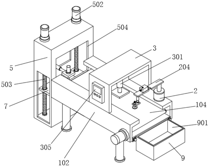
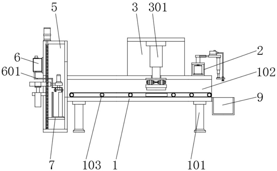
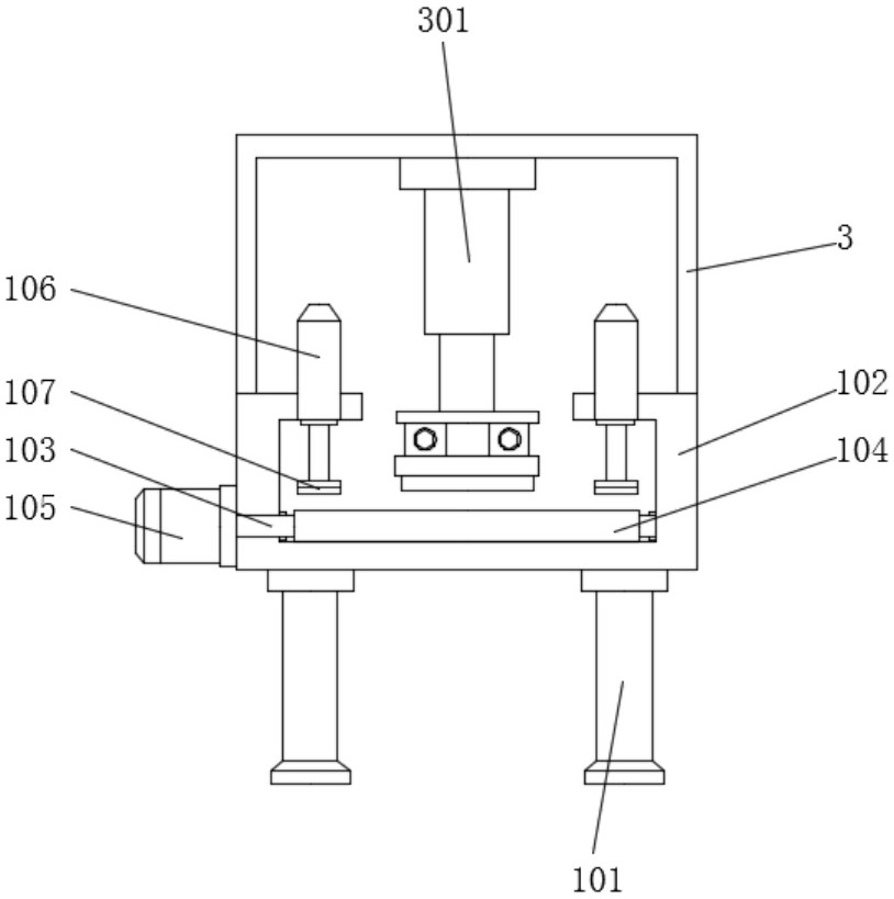
[0040] Embodiment 1, including a support plate 1, the bottom of the support plate 1 is equipped with a fixed column 101 through bolts, and the fixed column 101 supports the support plate 1 on the top to ensure that the support plate 1 remains stable, and it is convenient for the support plate 1 to support the support frame 102 on the top. Support, the inner side of the support frame 102 is installed with a rotating rod 103, the outer side of the rotating rod 103 is equipped with a transmission belt 104, the outer wall of the supporting frame 102 is equipped with a motor 105, the output end of the motor 105 is connected with one end of the rotating rod 103, and the supporting frame The top of 102 is installed with extruding rod 106 through, and extruding pad 107 is installed on the bottom of extruding rod 106, and the top of supporting plate 1 is symmetrically installed with two groups of supporting frames 102, and the top of supporting frame 102 is equipped with fixed frame 3, ...

Embodiment 2

[0042] Embodiment 2 includes a support plate 1, a fixed box 2 is installed on the top of the support frame 102, a driving motor 201 is installed inside the fixed box 2, and the fixed box 2 supports the driving motor 201 to ensure that the driving motor 201 can run smoothly. The output end of 201 is equipped with rotary platform 202 through connecting rod, and the top of rotary platform 202 is equipped with support column 203, and the top of support column 203 is equipped with support bar 204, and the inside of support bar 204 is equipped with adjustment arm 205, and the adjustment arm One end of 205 is equipped with movable arm 206, and the bottom of movable arm 206 is equipped with telescopic arm 207, and the bottom end of telescopic arm 207 is equipped with mounting table 208, and the top of movable arm 206 is equipped with the first suction pump 4, the first suction pump 4 An air outlet 401 is installed on the top of the first air suction pump 4, a first air suction pipe 402...

Embodiment 3

[0044]Embodiment 3 includes a support plate 1, a loading rack 5 is installed on the other side of the support plate 1, and the side of the loading rack 5 away from the support plate 1 is connected with a door body 501 through a hinge. When materials need to be placed, Open the door body 501 to facilitate workers to place the chips. The door body 501 is located on the side outside the loading rack 5 and is equipped with a second air pump 6 through bolts. The bottom of the second air pump 6 is equipped with a second air suction pipe 601. The air extraction pipe 601 runs through the inner side of the movable groove 505, the bottom end of the second air extraction pipe 601 is equipped with a splicing joint 602, the side of the loading frame 5 close to the support plate 1 is provided with a feeding window 504, and the inner side of the door body 501 is provided with a movable window 504. Groove 505, and movable groove 505 is positioned at the below of second suction pump 6, and door...


PUM


Abstract

An electronic chip punching tool with a clamping structure is disclosed in the invention, and comprises a supporting plate, two supporting frames are symmetrically installed at the top of the supporting plate, a fixing box is installed at the tops of the supporting frames, a driving motor is installed in the fixing box, a rotating table is installed at the output end of the driving motor through a connecting rod, a fixing frame is installed on the top of the supporting frame, a waste collecting box is installed on one side of the supporting frame through bolts, and a damping pad is installed on the inner side of the waste collecting box. A feeding frame is installed on the other side of the supporting plate. A threaded rod is installed, in the feeding process, a servo motor operates to drive the threaded rod to rotate, the threaded rod rotates to drive an internal thread lantern ring on the outer side to ascend through threads, and the internal thread lantern ring ascends to drive a lifting table to ascend, so that the height of the tool is adjusted, it is guaranteed that chips on the uppermost layer of the tool are kept at the proper height all the time, and feeding of the tool is facilitated.

Description

technical field [0001] The invention relates to the technical field of electronic chip processing, in particular to a punching tool for electronic chips with a clamping structure. Background technique [0002] An electronic chip is an integrated circuit. In electronics, it is a way to miniaturize a circuit. An integrated circuit is the core of a microprocessor or a multi-core processor. It can control a series of intelligent electronic devices such as computers and mobile phones. It is promoting the development of modern information society An important tool. In the process of chip production, the entire chip block needs to be cut into individual small chips. [0003] The defective that punching tool exists in the prior art is: [0004] 1. The comparative document CN212113637U discloses a chip punching device for electronic product processing, "its structure includes a main body, a placement slot, a receiving plate, a splint, a controller, a power cord, a processing mechani...

Claims


Application Information

Patent Timeline
Patent Type & Authority Applications(China)
IPC IPC(8): B28D5/04B28D7/00B28D7/04H01L21/304H01L21/683
CPCB28D5/042B28D5/0058B28D5/0082B28D5/0094H01L21/304H01L21/6838
Inventor 周明
Owner NANTONG MINICHIP MICRO ELECTRONICS
Why Eureka
Try Eureka