Asphalt pavement composite structure and construction method thereof

A composite structure and asphalt pavement technology, applied in infrastructure engineering, roads, roads, etc., can solve the problem of uneven thickness, achieve uniform bearing force, improve wildness, and reduce the effect of gravel slipping

Active Publication Date: 2022-02-11
HANGZHOU GUANGHUA ROAD & BRIDGE ENG
View PDF29 Cites 0 Cited by
  • Summary
  • Abstract
  • Description
  • Claims
  • Application Information

AI Technical Summary

Problems solved by technology

[0004] With regard to the related technologies mentioned above, the inventor believes that when gravel is paved on a roadbed with a relatively large slope, the gravel at a high place is easily affected by gravity. Rolling down, resulting in a thinner subbase at the top of the embankment and a thicker subbase at the bottom of the embankment, resulting in uneven thickness

Method used


Image

  • Asphalt pavement composite structure and construction method thereof
  • Asphalt pavement composite structure and construction method thereof
  • Asphalt pavement composite structure and construction method thereof

Examples


Embodiment 1

[0057] Embodiment 1 also discloses a construction method of asphalt pavement composite structure, such as Figure 7 shown, including the following steps:

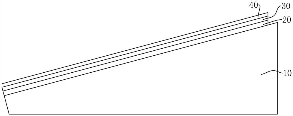
[0058] S1, rolling the inclined roadbed 10: use a road roller to roll the inclined roadbed 10 3 times at a rolling speed of 7-10 meters per minute to improve surface smoothness.

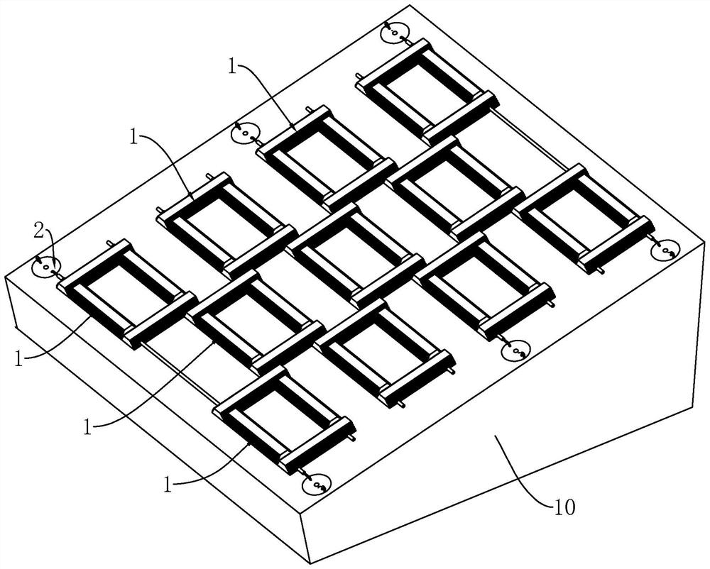
[0059] S2. Positioning and marking: use lime powder to draw lines along the width of the inclined roadbed 10 to determine the position of the steel pipe 21 .

[0060] S3. Paving the blocking frame 1: Pre-arrange the position of the blocking frame 1 according to the marking position, and then pre-shape the blocking frame 1 by piercing the steel pipe 21 to ensure the control of the blocking frame 1 Neatly, then press the blocking frame 1 to ensure that the blocking frame 1 fits the surface of the inclined roadbed 10, and then tighten the limit ring 211 so that the limit ring 211 is tight against the outside of the blocking frame 1, and the blocking...

Embodiment 2

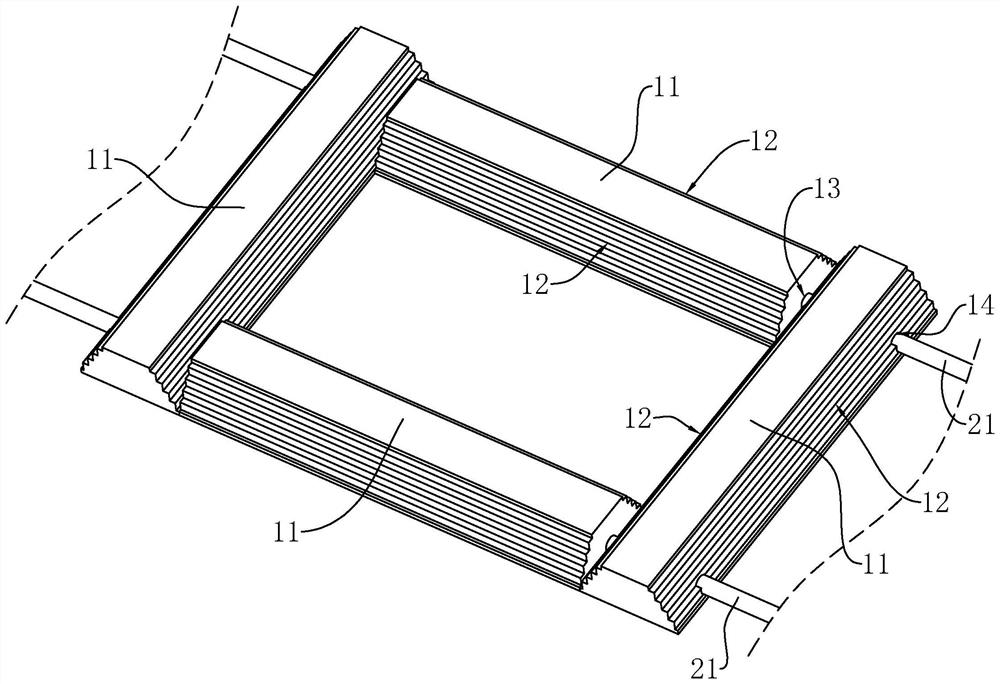
[0065] Embodiment 2, make the following setting on the basis of embodiment 1, such as Figure 8 As shown, there is a notch at the center of the upper part of the first blocking strip, the notch is strip-shaped, and the length direction of the notch is set along the length direction of the inclined roadbed 10, and the notch goes deep into the first perforation 13, which is the first water passage Hole 15, steel pipe 21 is provided with the second water hole (not marked among the figure), and the second water hole is communicated with the first water hole 15, and the two ends of steel pipe 21 are connected with drainage pipe 27, and drainage pipe 27 uses In connection with the groundwater delivery system.

[0066] When there is accumulated water in the base layer 20, the accumulated water will pass through the first bucket water hole, the second water hole, the steel pipe 21 in sequence, and finally be discharged into the underground transportation system by the drain pipe 27, t...


PUM


Abstract

The invention relates to an asphalt pavement composite structure and a construction method thereof. The main scheme is that the asphalt pavement composite structure comprises an inclined roadbed, and a subbase layer and an asphalt surface layer are sequentially laid on the upper surface of the inclined roadbed. A plurality of blocking frame bodies and fixing assemblies used for fixing the blocking frame bodies are further laid on the upper surface of the inclined roadbed, the thickness of the blocking frame bodies is smaller than or equal to that of the subbase layer, and the hollow positions of the blocking frame bodies are containing areas used for evenly distributing gravel of the subbase layer. The blocking frame body is arranged, the containing areas of the blocking frame body are used for containing broken stones, so that the broken stones are limited, the situation that the broken stones slide down is effectively reduced, the broken stones are evenly distributed in the multiple containing areas, and the thickness uniformity of the subbase layer can be improved.

Description

technical field [0001] The present application relates to the field of asphalt pavement construction, in particular to an asphalt pavement composite structure and a construction method thereof. Background technique [0002] Asphalt pavement refers to various types of road surfaces that are paved with road asphalt materials mixed with mineral materials. Asphalt binder improves the ability of paving aggregates to resist road damage from driving and natural factors, making the road smooth, less dusty, impermeable and durable. Therefore, asphalt pavement is the most widely used high-grade pavement in road construction. [0003] The asphalt pavement structure in the related art includes a roadbed, a subbase, and an asphalt surface layer, wherein the subbase is paved with crushed stones to assist in bearing gravity. [0004] In view of the above-mentioned related technologies, the inventor believes that when paving gravel on a roadbed with a large slope, the gravel at a high pla...

Claims


Application Information

Patent Timeline
Patent Type & Authority Applications(China)
IPC IPC(8): E01C3/00E01C3/04E01C11/22E01C7/18E02D5/74
CPCE01C3/00E01C3/006E01C3/04E01C11/227E01C7/18E02D5/74E02D2250/0046E02D2600/30Y02A30/60
Inventor 熊伟明唐迪成留邵君孟月苗赵利峰
Owner HANGZHOU GUANGHUA ROAD & BRIDGE ENG
Why Eureka
Try Eureka