Photonic crystal fiber transmission system suitable for ultra-long distance transmission

A photonic crystal fiber, transmission system technology, applied in transmission systems, electromagnetic wave transmission systems, multi-layer core/cladding fibers, etc. Low nonlinear coefficient, easy to achieve effect

Inactive Publication Date: 2022-02-11
HUNAN UNIV
View PDF7 Cites 0 Cited by
  • Summary
  • Abstract
  • Description
  • Claims
  • Application Information

AI Technical Summary

Problems solved by technology

However, due to the complex structure, it cannot be manufactured commercially

Method used


Image

  • Photonic crystal fiber transmission system suitable for ultra-long distance transmission
  • Photonic crystal fiber transmission system suitable for ultra-long distance transmission
  • Photonic crystal fiber transmission system suitable for ultra-long distance transmission

Examples


Embodiment Construction

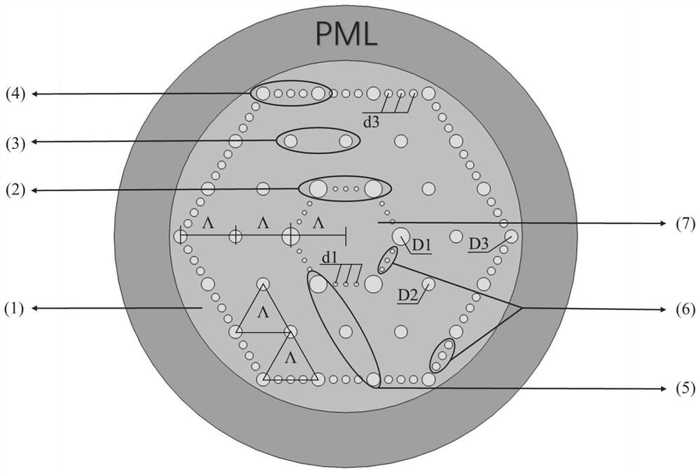
[0041] In order to deepen the understanding of the present invention, the present invention will be further described below in conjunction with examples, which are only used to explain the invention, and do not constitute a limitation to the protection scope of the present invention. This embodiment provides a photonic crystal fiber transmission system suitable for ultra-long-distance transmission, such as figure 1 As shown, the system consists of five modules, the transmitter module, the receiver module, the optical signal transmission module, the coupling module, and the dispersion compensation module. The photonic crystal fiber used in the transmission system includes a base material 1, an inner dielectric ring 2, an intermediate dielectric ring 3, an outer dielectric ring 4, a main dielectric hole 5, a secondary dielectric hole 6, and a fiber core 7. The layer dielectric rings are arranged in a hexagonal quasi-periodic arrangement in the center of the base material, the mi...


PUM


Abstract

The invention provides an ultra-flat photonic crystal fiber transmission system, and a photonic crystal fiber used by the transmission system comprises a substrate material, inner-layer dielectric rings, middle-layer dielectric rings, outer-layer dielectric rings, primary dielectric holes, secondary dielectric holes and a fiber core; the inner-layer dielectric rings are arranged in a hexagonal quasi-periodic manner at the center of the substrate material, the middle-layer dielectric rings are arranged in a hexagonal periodic manner, and the outer-layer dielectric rings are arranged in a hexagonal quasi-periodic manner. The system comprises two photonic crystal fibers, one near-zero positive dispersion photonic crystal fiber (P1) is used for signal transmission, the other large negative dispersion photonic crystal fiber (P2) is used for dispersion compensation, and for the listed embodiments, in the wave band of 1260-1625 nm, dispersion fluctuations are (P1) 0.32 +/-0.17 ps/(nm-km) and (P2)-15.57 +/-0.37 ps/(nm-km) respectively; for optical fibers for transmitting signals, the nonlinear coefficient is lower than 1.1 (W-1. Km <-1 >), the numerical aperture is larger than 0.189, the limited loss is lower than 0.09 dB/km, and the optical fiber has great potential in DWDM systems, such as ultra-long-distance seabed transmission and the like.

Description

technical field [0001] The invention belongs to the technical field of ultra-flat photonic crystal fibers, and relates to photonic crystal fibers for ultra-long-distance transmission systems. Background technique [0002] Optical fiber communication system consists of optical transmitter, optical receiver, optical fiber or optical cable, repeater, optical fiber connector, coupler and other parts. [0003] The real development of modern optical communication is in the past thirty or forty years, in which the birth of lasers and optical fibers played a leading role. In 1960, Maiman invented the ruby ​​laser. The strong coherent light generated by the laser provided a reliable light source for modern optical communication. Early optical communication was transmitted through the atmosphere, but it was quickly eliminated due to large external interference and replaced by optical fiber transmission. [0004] In 1970, Corning Corporation developed an optical fiber with a loss of ...

Claims


Application Information

Patent Timeline
Patent Type & Authority Applications(China)
IPC IPC(8): G02B6/02G02B6/036H04B10/2525H04B10/2543
CPCG02B6/02361G02B6/02371G02B6/02228G02B6/03638H04B10/2525H04B10/2543
Inventor 杨华毛雨澄黄颖
Owner HUNAN UNIV
Why Eureka
Try Eureka