Micro-channel device for heat dissipation of high-power semiconductor chip and processing method

A chip heat dissipation and processing method technology, which is applied to semiconductor devices, semiconductor/solid-state device components, electric solid-state devices, etc., can solve problems such as low thermal conductivity, overheating and burning of chips, and high pressure requirements of water pump systems to ensure thermal conductivity. , Material consistency is good, the effect of improving heat dissipation efficiency

Pending Publication Date: 2022-02-11
HEFEI SHENGDA ELECTRONIC TECH IND CO LTD
View PDF0 Cites 0 Cited by
  • Summary
  • Abstract
  • Description
  • Claims
  • Application Information

AI Technical Summary

Problems solved by technology

[0002] With the increase of chip power and the improvement of integration in the semiconductor industry, the heating power of a single chip has increased significantly. The existing air-cooled and water-cooled heat dissipation technologies can no longer meet the heat dissipation requirements of a single higher-power chip.
In addition, the cooling performance of traditional water-cooling devices is limited by the water flow rate. If the water flow rate is continuously increased, a large water pressure will be formed inside the channel, and the inner cavity channel is difficult to meet the stress caused by the water flow pressure. Long-term use will lead to The internal channel of the radiator fails, which leads to the failure of water cooling and heat dissipation, and eventually causes the chip to overheat and burn, affecting the reliability of the overall device
In addition, the pressure demand of the water pump system outside the microchannel is relatively large, and the cost is also greatly increased.
Moreover, the existing water-cooling devices are mostly processed by silver-copper brazing, and silver-copper brazing is due to the brazing material Ag 72 Cu 28 The thermal conductivity of the device is usually lower than that of the device body material, so the heat dissipation efficiency will also be limited

Method used


Image

  • Micro-channel device for heat dissipation of high-power semiconductor chip and processing method
  • Micro-channel device for heat dissipation of high-power semiconductor chip and processing method
  • Micro-channel device for heat dissipation of high-power semiconductor chip and processing method

Examples


Embodiment 1

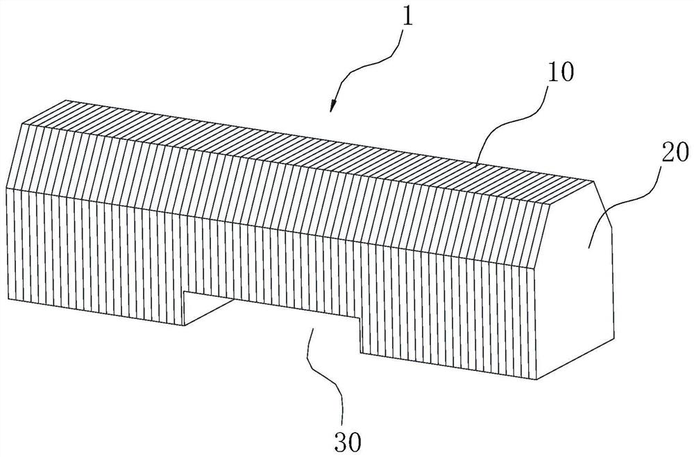
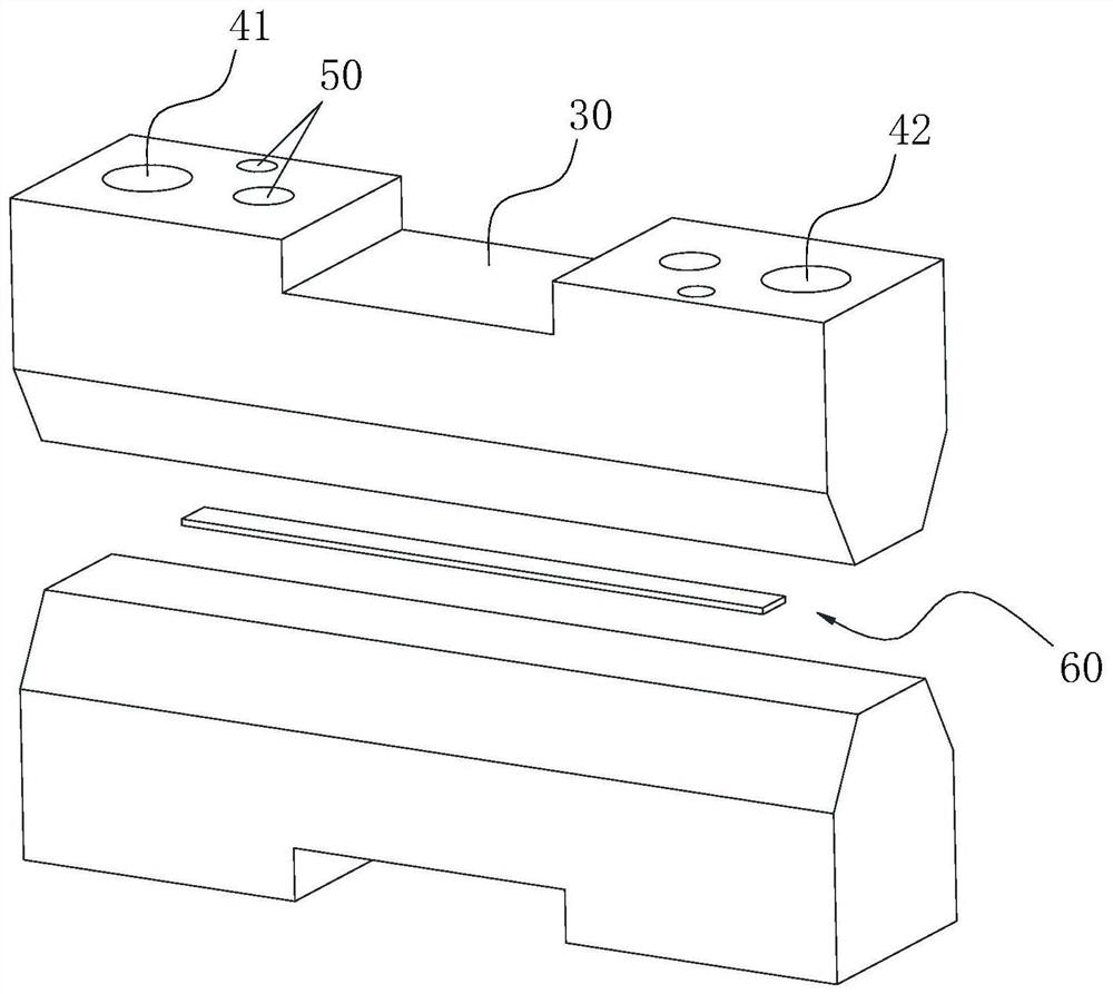
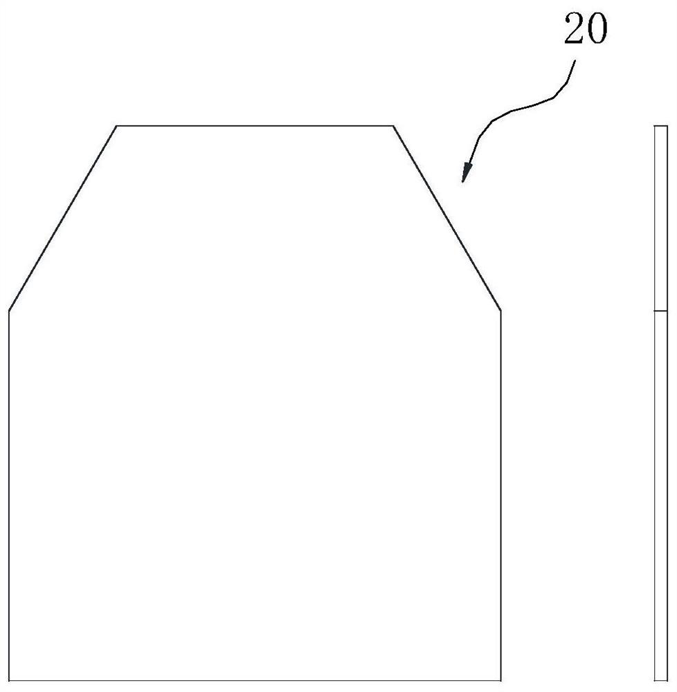
[0053] Such as figure 1 , Figure 3-5 Shown, a kind of microchannel device 1 that is used for the heat dissipation of high-power semiconductor chip, comprises the heat dissipation inner core that is formed by the staggered arrangement of several heat dissipation fins 10 and the blocking sheet 20 that is arranged on the front and rear ends of the described heat dissipation inner core; Heat dissipation fin 10 and The blocking pieces 20 are in the shape of a hexagon including two adjacent right angles and four inner obtuse angles, and the shape of the cooling fins 10 enables the microchannel device to avoid adjacent components during installation. The heat sink 10 and the blocking sheet 20 are both made of oxygen-free copper, and both have a thickness of 0.3 mm. The center of the bottom of the micro-channel device 1 is also provided with a groove 30 for positioning and installation. The groove 30 is as wide as the micro-channel device 1 but slightly shorter in length.

[0054] ...

Embodiment 2

[0062] A processing method for a microchannel device 1 for heat dissipation of a high-power semiconductor chip, the steps are as follows:

[0063] S1. Positioning on the oxygen-free copper plate and chemically etching out the hollow groove required for the heat sink 10, and then cutting the etched oxygen-free copper plate into the required heat sink 10;

[0064] S2. cutting the unetched oxygen-free copper plate to obtain the blocking sheet 20;

[0065] S3. Place the blocking sheet 20 on the fixture, then place the cooling fins 10 according to the required stacking order and quantity of the cooling fins 10, and finally place the blocking sheet 20 at the end;

[0066] S4. Put the arranged heat sink 10 together with the fixture into a diffusion welding furnace for diffusion welding, and the welding temperature is 900°C-1100°C;

[0067] S5. The welded product is subjected to secondary cutting, and the groove 30 is processed to obtain the final desired shape of the microchannel de...

Embodiment 3

[0073] Utilize the microchannel device prepared by the present invention to compare with the cooling device that changes the shape of the microchannel in the device. The appearance and material of the microchannel cooling device for comparison are consistent with the microchannel device prepared by the present invention, but its water flow channel is integrally processed. into, respectively, a rhombus straight and a rectangular straight.


PUM

PropertyMeasurementUnit
thicknessaaaaaaaaaa
surface smoothnessaaaaaaaaaa

Abstract

The invention relates to the field of production and packaging of electronic component shells, in particular to a micro-channel device for heat dissipation of a high-power semiconductor chip and a processing method of the micro-channel device. The micro-channel device comprises a heat dissipation inner core formed by arranging a plurality of heat dissipation sheets in a staggered mode and blocking sheets arranged at the front end and the rear end of the heat dissipation inner core. The heat dissipation sheet is in a hexagon shape comprising two adjacent right angles and six inner obtuse angles, a hollow groove is formed in the heat dissipation sheet, and a water passing channel is formed in a radiating chip through the hollow groove; and the micro-channel device further comprises a groove formed in the bottom, a water inlet hole and a water outlet hole, wherein the water inlet hole and the water outlet hole are communicated with the water passing channel. According to the micro-channel device provided by the invention, the problems that the root strength of the internal heat dissipation fins is insufficient and the heat dissipation fins are easy to break when the heat dissipation channel in the traditional heat dissipation device is used under the large-pressure cold medium flow, so that the overall heat dissipation is influenced, and the chip fails can be overcome.

Description

technical field [0001] The invention relates to the technical field of heat dissipation of semiconductor chips, in particular to a microchannel device for heat dissipation of high-power semiconductor chips and a processing method thereof. Background technique [0002] With the increase of chip power and integration in the semiconductor industry, the heating power of a single chip has increased significantly, and the existing air-cooled and water-cooled heat dissipation technologies can no longer meet the heat dissipation requirements of a single higher-power chip. In addition, the cooling performance of traditional water-cooling devices is limited by the water flow rate. If the water flow rate is continuously increased, a large water pressure will be formed inside the channel, and the inner cavity channel is difficult to meet the stress caused by the water flow pressure. Long-term use will lead to The internal channel of the radiator fails, which leads to the failure of wate...

Claims


Application Information

Patent Timeline
Patent Type & Authority Applications(China)
IPC IPC(8): H01L23/473B23P15/26B23P15/00
CPCH01L23/473B23P15/26B23P15/00
Inventor 黄海李建国王凤史常东
Owner HEFEI SHENGDA ELECTRONIC TECH IND CO LTD
Why Eureka
Try Eureka