Laser gyroscope teaching demonstration system

A technology of laser gyro and demonstration system, applied in the field of laser gyro teaching demonstration system, can solve the problems of many complete sets of equipment, inconvenient opening time, and few demonstration experiments of the laser gyro demonstration system, so as to achieve easy understanding and application, convenient management and placement, The effect of simplifying the teaching process

Pending Publication Date: 2022-02-15
湖南二零八先进科技有限公司
View PDF0 Cites 1 Cited by
  • Summary
  • Abstract
  • Description
  • Claims
  • Application Information

AI Technical Summary

Problems solved by technology

[0003] However, at present, the laser mode adjustment and Sagnac effect in the undergraduate teaching of colleges and universities are mainly based on principle explanation and formula derivation, and there are few corresponding demonstration experiments.
On the one hand, it is because there are many complete sets of equipment in the laser gyroscope demonstration system (helium-neon laser tube, laser mirror, single-mode calibrator, photodetector, frequency counter, oscilloscope, etc.) and the cost is high; The operation requirements of the operator are high, and it is difficult to control the process to obtain ideal experimental results, so it is not suitable for setting up experimental courses with limited time.

Method used


Image

  • Laser gyroscope teaching demonstration system
  • Laser gyroscope teaching demonstration system
  • Laser gyroscope teaching demonstration system

Examples


Embodiment 1

[0048] The system of the present invention can explore the relationship between the cavity length of the straight cavity mode and the spacing of the longitudinal mode. This experiment uses a laser module, a cavity tuning module, and a control and display device.

[0049] Specific steps are as follows:

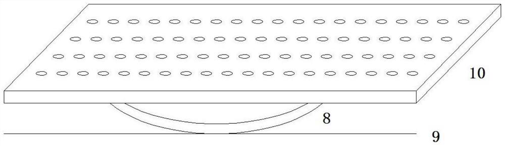
[0050] Such as Figure 4 As shown, the collimating laser 3, the helium-neon laser tube 2, the diaphragm 4, the first reflector 1-1 and the second reflector 1-2 are installed on the base 9 with the adjustment bracket (see image 3 ), the base is punched with precise matrix installation holes, where the first reflector 1-1 is placed on the far left, and the helium-neon laser tube 2 with the Brewster window is installed on the right. The first reflection mirror 1-1 and the second reflection mirror 1-2 are total reflection mirrors, preferably, the first reflection mirror 1-1 is a concave mirror, and the second reflection mirror 1-2 is a plane mirror.

[0051] (1) Turn on the col...

Embodiment 2

[0058] The system of the present invention can also be used to demonstrate the tuning and collimation process of the ring resonant cavity, and the system needs to use a laser module and a cavity tuning module.

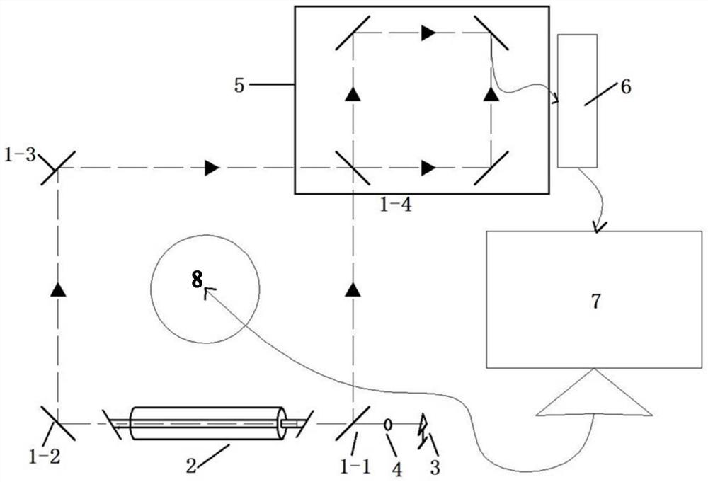
[0059] Such as figure 2 Shown:

[0060] (1) Set the collimation reference laser line

[0061] Fix the collimated laser 3 on the adjustment platform, turn it on, emit the laser beam, adjust the pitch angle of the indicator laser 3, make the collimated laser beam parallel to the precision optical flat plate 10, and be in a horizontal state. This collimated laser is used as the collimated reference laser line .

[0062] (2) Adjust the He-Ne laser tube 2 with the Brewster window to be horizontal

[0063] (3) as shown in embodiment 1, make the helium-neon laser tube 2 of band Brewster window go out light

[0064] At this time, it can be determined that the He-Ne laser tube 2 with the Brewster window, the center of the aperture 4 and the light of the collimator 3 are in...

Embodiment 3

[0070] The system of the present invention can also be used to demonstrate and explore the relationship between the cavity length of the annular cavity mode and the spacing of the longitudinal mode.

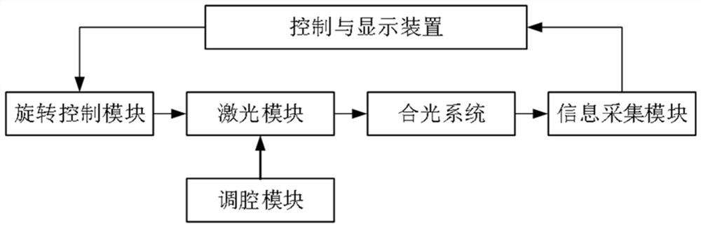
[0071] Such as figure 2 As shown, the system uses a laser module, a cavity tuning module, a light combination system 5 , an information collection module 6 and a control and display device 7 .

[0072] Adjust each equipment according to embodiment 2. Connected to the combined light system 5, the resonant light generates interference light, and the interference light signal of the system is collected through the information collection module.

[0073] Such as Image 6 with Figure 7 As shown, the software in the control and display device 7 can directly store data, plot and analyze data.

[0074] Change the cavity length of the annular cavity mode, observe the change of the interval of the longitudinal mode on the computer software page, and explore the relationship between t...


PUM


Abstract

A laser gyroscope teaching demonstration system comprises a rotation control module used for controlling rotation of a laser gyroscope, a laser module which can emit laser, a cavity adjusting module which is matched with the laser module to collimate the laser gyroscope reflector, an information acquisition module which is used for acquiring the image and photoelectric information of the laser module, and a control and display device which is used for displaying the information acquired by the information acquisition module and outputting control parameters to the rotation control module. The system further comprises a light combination system which is used for adjusting the position of a light combination prism on the laser gyroscope reflector, interference light is generated by laser emitted by the laser module, and image acquisition and data acquisition of the information acquisition module are more efficient and accurate. The system is highly integrated and can be used for demonstrating various working modes and parameters of the laser gyroscope, and the teaching effect is improved.

Description

technical field [0001] The present invention relates to the technical field of laser gyroscopes, and more specifically, to a teaching and demonstration system for laser gyroscopes. Background technique [0002] Laser gyro is a sensor used to measure the angular rate of moving objects, and it is one of the commonly used sensor types in modern inertial navigation technology. The laser mode adjustment and Sagnac effect demonstration involved in the basic field of laser gyroscope are important basic concepts in the application of laser gyroscope technology. In the production and application of many gyroscopes, it is necessary to learn the laser mode and Sagnac effect first, and the theory involved is very Strong, but the conclusions mentioned in theoretical classes in university courses are generally obtained through complex mathematical derivations, the process is very abstract, and students learn obscure and boring. In order to strengthen students' understanding and applicati...

Claims


Application Information

Patent Timeline
Patent Type & Authority Applications(China)
IPC IPC(8): G09B23/22
CPCG09B23/22
Inventor 王飞卢广锋王凡
Owner 湖南二零八先进科技有限公司
Why Eureka
Try Eureka