Single photon emission tomography device
A single-photon emission and tomographic imaging technology, which is applied in nuclear technology and application fields, can solve problems such as poor collimation effect of the collimator, affecting the detection efficiency of SPECT, and large size, and achieves the effect of reducing the size
- Summary
- Abstract
- Description
- Claims
- Application Information
AI Technical Summary
Problems solved by technology
Method used
Image

Examples
Embodiment 1
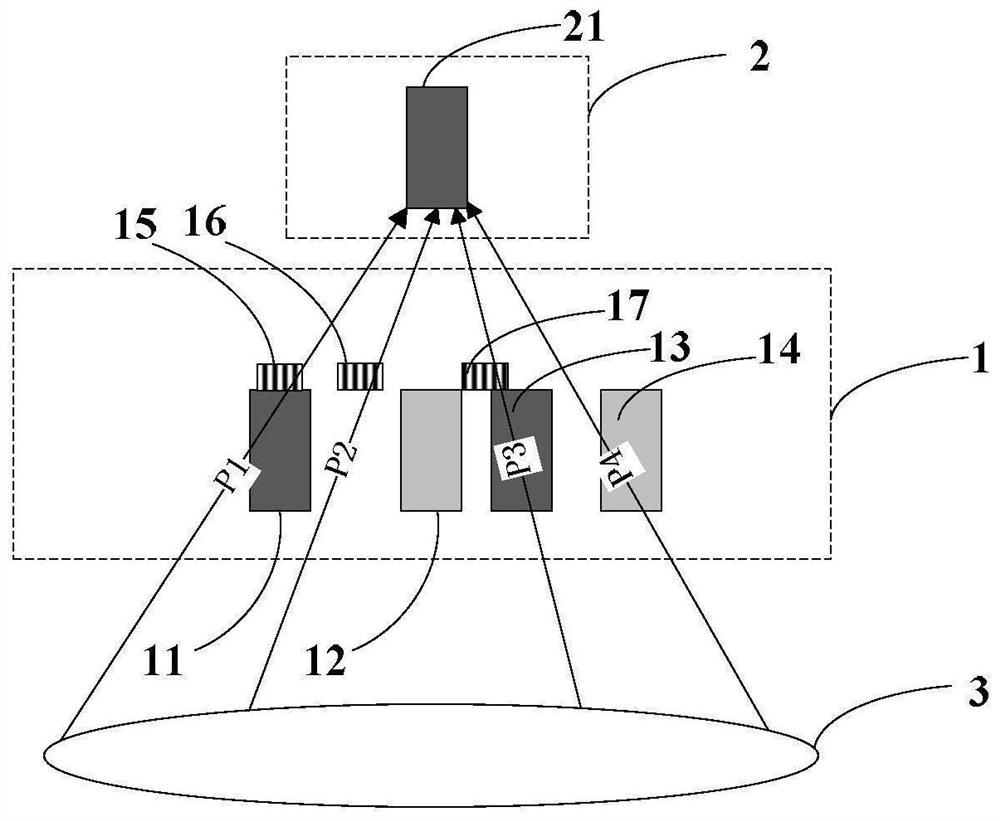
[0033] In this example, if figure 1 As shown, the radionuclide in the detected object (such as the human body 3) produces gamma photons, and the imaging device includes and is not limited to two detector layers, which are distributed in front and rear layers along the gamma photon transmission direction outside the human body, Wherein, the detector layer ahead along the photon transmission direction is the first detector layer 1, the detector layer behind the photon transmission direction is the second detector layer 2, and the previous detector layer (the first detector layer ) is closer to the human body than the subsequent detector layer (the second detector layer). The first detector layer 1 includes four independent scintillation crystal strips 11, 12, 13, 14 (although the present embodiment is an independent scintillation crystal strip, the quantity is several, but in fact also can adopt the splicing scintillation crystal strip or both Several combinations) and three Si...
Embodiment 2
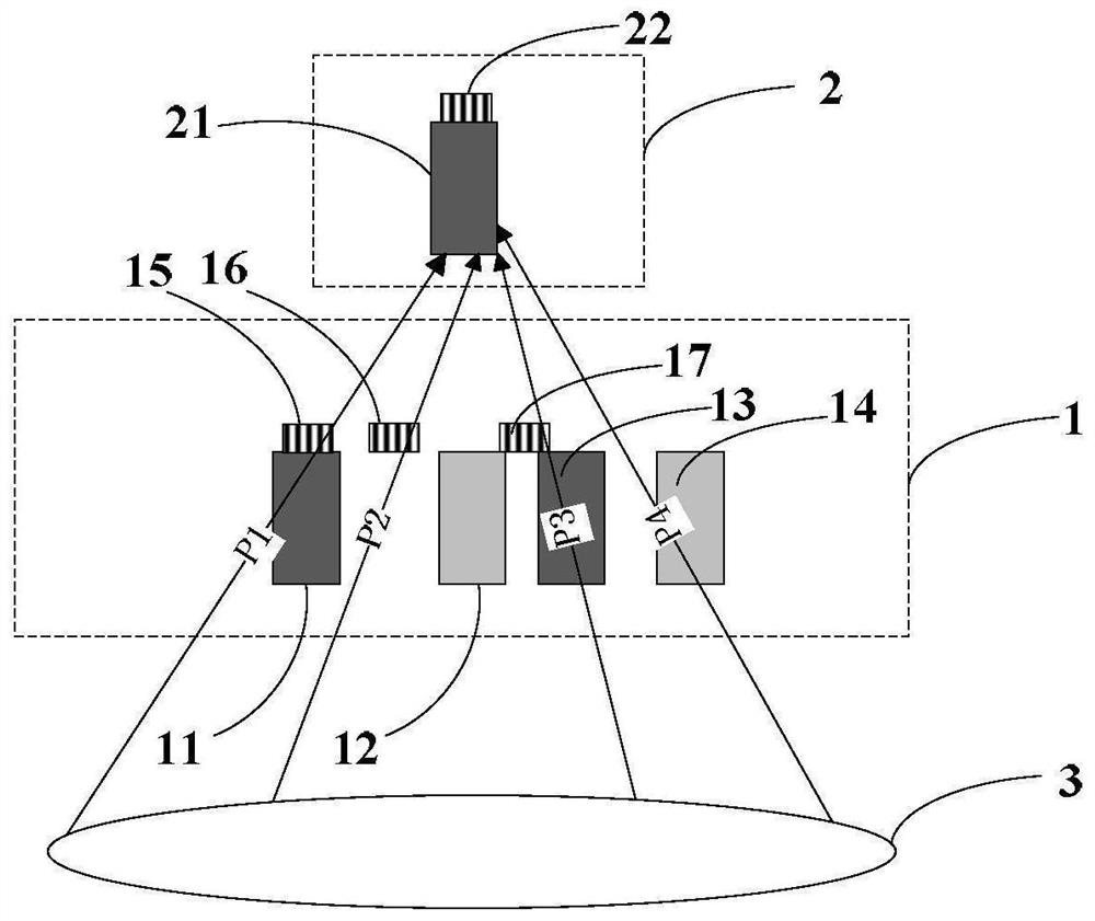
[0040] In this example, if figure 2 As shown, the radionuclide in the object to be detected (such as the human body 3) produces gamma photons, and the imaging device includes two detector layers, which are distributed in front and rear layers along the movement direction of the gamma photons outside the human body. The detector layer in front of the photon movement direction is the first detector layer 1, the detector layer behind the photon movement direction is the second detector layer 2, and the front detector layer (first detector layer) is more The last detector layer (the second detector layer) is closer to the human body. The first detector layer 1 includes four independent scintillation crystal strips 11, 12, 13, 14 and three SiPM devices 15, 16, 17 (15, 16, 17 can also use APD optoelectronic devices), the second detector layer 2 includes a scintillation crystal strip 21 and a PMT device 22 (22 is not limited to a PMT device, and can be any type of optoelectronic de...
Embodiment 3
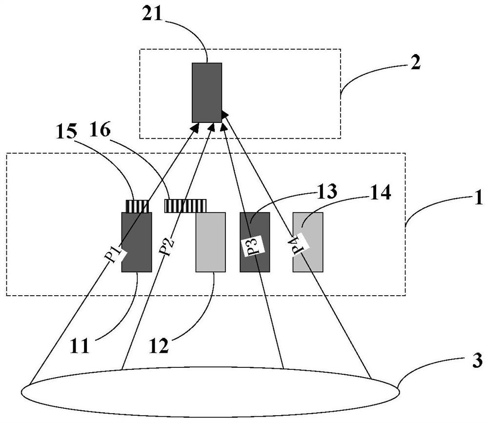
[0044] In this example, if image 3 As shown, the radionuclide in the object to be detected (such as the human body 3) produces gamma photons, and the imaging device includes two detector layers, which are distributed in front and rear layers along the movement direction of the gamma photons outside the human body. The detector layer in front of the photon movement direction is the first detector layer 1, the detector layer behind the photon movement direction is the second detector layer 2, and the front detector layer (first detector layer) is more The last detector layer (the second detector layer) is closer to the human body.
[0045] The first detector layer is used to block and collimate photons moving towards the second detector layer, that is, to serve as a collimator. Traditional SPECT cannot use a collimator with a high penetration ratio due to its own limitations. This disclosure uses the front detector layer as a collimator to cause its photon collimation effect o...
PUM
 Abstract
Description
Claims
Application Information
 - Generate Ideas
- Intellectual Property
- Life Sciences
- Materials
- Tech Scout
- Unparalleled Data Quality
- Higher Quality Content
- 60% Fewer Hallucinations
Browse by: Latest US Patents, China's latest patents, Technical Efficacy Thesaurus, Application Domain, Technology Topic, Popular Technical Reports.
© 2025 PatSnap. All rights reserved.Legal|Privacy policy|Modern Slavery Act Transparency Statement|Sitemap|About US| Contact US: help@patsnap.com