Extraction device for cell-free protein synthesis

A cell-free protein and extraction device technology, which is applied in the field of cell-free protein synthesis extraction devices, can solve the problems of low extraction efficiency and easy drop of test tubes, and achieve the effects of convenient separation and extraction, simple use, and avoiding losses

Active Publication Date: 2022-02-25
徐州支点生物技术研究院有限公司 +1
View PDF8 Cites 0 Cited by
  • Summary
  • Abstract
  • Description
  • Claims
  • Application Information

AI Technical Summary

Problems solved by technology

[0004] The purpose of the present invention is to solve the shortcomings of the prior art that the test tube is easy to drop and the extraction efficiency is low, and proposes an extraction device for cell-free protein synthesis

Method used


Image

  • Extraction device for cell-free protein synthesis
  • Extraction device for cell-free protein synthesis
  • Extraction device for cell-free protein synthesis

Examples


Embodiment 1

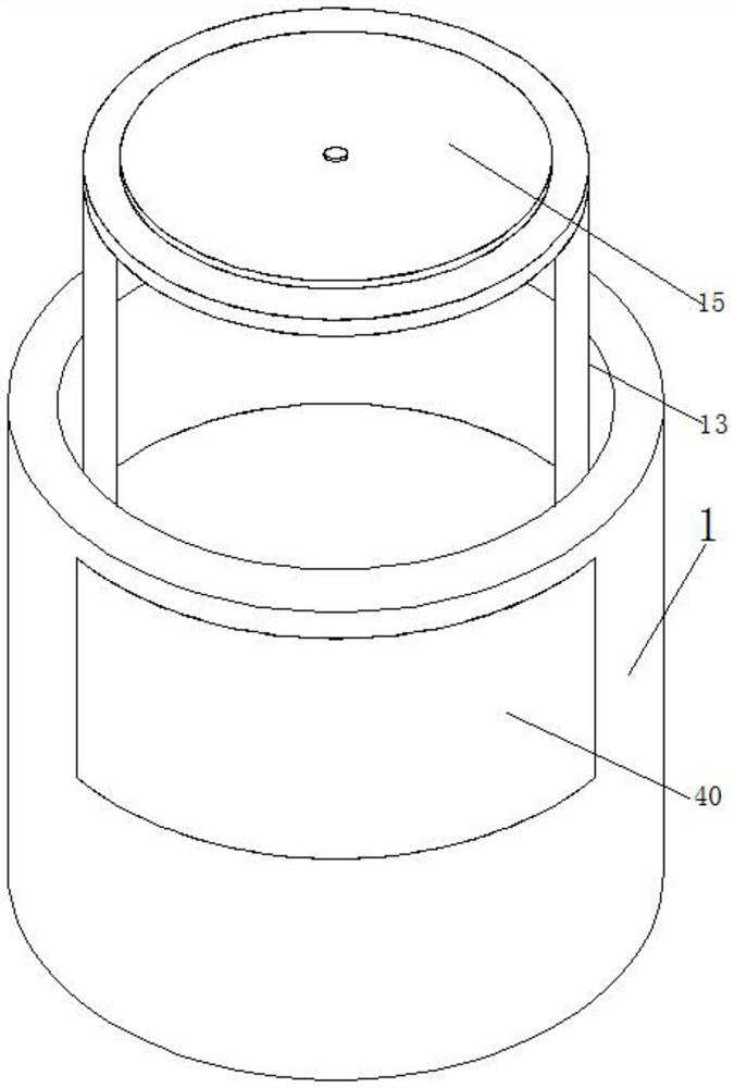
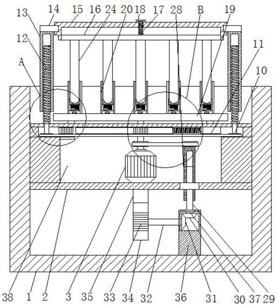
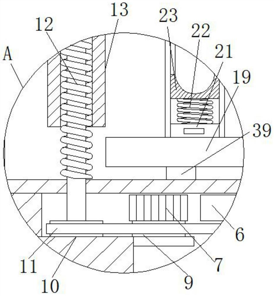
[0028] refer to Figure 1-6 , an extraction device for cell-free protein synthesis, comprising a bottom box 1, a bearing plate 2 is slidably installed in the bottom box 1, an accommodation cavity 38 is opened on the loading plate 2, a motor 3 is fixedly installed in the accommodation cavity 38, and a motor 3 A rotating rod 4 is fixedly installed on the output shaft, a first gear 5 is fixedly installed on the rotating rod 4, a double-sided rack 6 is meshed on the first gear 5, and a second gear 7 is installed rotating in the accommodation chamber 38, and the second gear 7 meshes with the double-sided rack 6, a first spring 8 is fixedly installed on one side of the double-sided rack 6, and one end of the first spring 8 is fixedly connected with the inner wall of the accommodation cavity 38, and a clamping mechanism is arranged on the bearing plate 2 , the bottom box 1 is provided with a centrifugal mechanism, the third pulley 25 is fixedly installed on the rotating rod 4, the fo...

Embodiment 2

[0040] refer to Figure 7 The difference with Embodiment 1 is that the vibrating mechanism includes a first bevel gear 30, which is fixedly connected with a rectangular rod 29, and a second bevel gear 31 is meshed with the first bevel gear 30, and the second bevel gear 31 is A moving rod 32 is fixedly installed, a disc 41 is fixedly installed on the moving rod 32, a round shaft 42 is fixedly installed on the disc 41, a mid-shaped plate 43 is slidably installed in the bottom box 1, and the inner wall of the round shaft 42 and the mid-shaped plate 43 slides Connection, the top plate 35 is fixedly installed on the middle plate 43, and the top plate 35 is fixedly connected with the bearing plate 2.

[0041] In the present invention, a vertical rail is arranged inside the bottom box 1, and the vertical rail is slidingly connected with the mid-shaped board 43, and the vertical rail can make the mid-shaped board 43 slide at a fixed position.

[0042] Working principle: When in use, ...


PUM


Abstract

The invention belongs to the technical field of extraction devices, particularly relates to an extraction device for cell-free protein synthesis, aims to solve the problems that an existing test tube is easy to fall off and low in extraction efficiency, and provides the following scheme: the extraction device comprises a bottom box, a bearing plate is slidably mounted in the bottom box, a containing cavity is formed in the bearing plate, and a motor is fixedly mounted in the containing cavity; a rotating rod is fixedly mounted on an output shaft of the motor, a first gear is fixedly mounted on the rotating rod, a double-sided rack is meshed with the first gear, a second gear is rotatably mounted in the containing cavity and meshed with the double-sided rack, and a first spring is fixedly mounted on one side of the double-sided rack; and one end of the first spring is fixedly connected with the inner wall of the containing cavity, and a clamping mechanism is arranged on the bearing plate. The extraction efficiency can be improved, test tubes can be prevented from being thrown out, unnecessary loss is avoided, use is easy, and operation is convenient.

Description

technical field [0001] The invention relates to the technical field of extraction devices, in particular to an extraction device for cell-free protein synthesis. Background technique [0002] The cell-free protein synthesis system is an in vitro system that uses exogenous mRNA or DNA as a template to supplement substrates and energy in the enzyme system of cell extracts to synthesize proteins. Compared with the traditional in vivo recombinant expression system, the in vitro cell-free synthesis system has many advantages, such as the ability to express special proteins that are toxic to cells or contain unnatural amino acids (such as D-amino acids), and can directly use PCR products as templates. Simultaneously synthesize multiple proteins in parallel to carry out high-throughput drug screening and proteomics research. [0003] Most of the extraction devices used for cell-free protein use centrifuge devices. The existing centrifuge devices directly insert the test tubes on t...

Claims


Application Information

Patent Timeline
IPC IPC(8): B04B5/04B04B7/00B04B15/00B04B9/02
CPCB04B5/0414B04B7/00B04B15/00B04B9/02
Inventor 韩鲲开雷连佳长岳珂马毅刘冉
Owner 徐州支点生物技术研究院有限公司
Why Eureka
Try Eureka