Rotary fermentation tank with high discharging efficiency
A fermenter and high-efficiency technology, which is applied to specific-purpose bioreactor/fermenter, bioreactor/fermenter combination, biochemical equipment, etc., can solve the problem of lack of effective umami ingredients in fish sauce, inconvenient discharge of fish sauce, The quality and efficiency of fish sauce are low, so as to prevent the loss of effective umami ingredients, avoid the reduction of histamine content, and shorten the fermentation time
- Summary
- Abstract
- Description
- Claims
- Application Information
AI Technical Summary
Problems solved by technology
Method used
Image
Examples
Embodiment 1
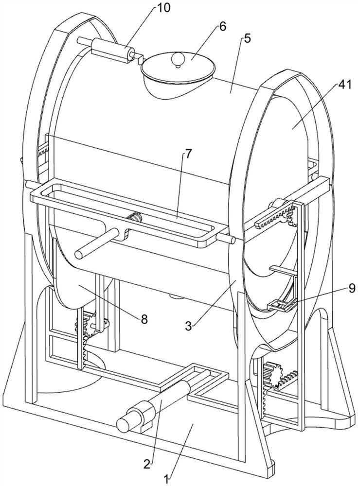
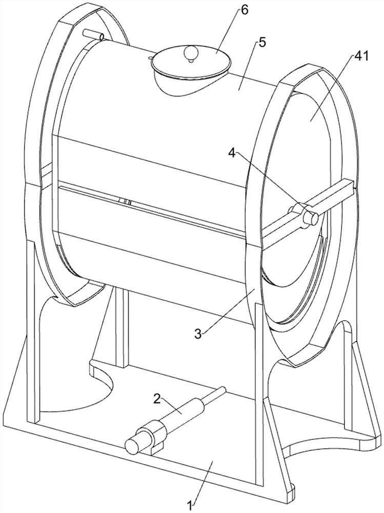
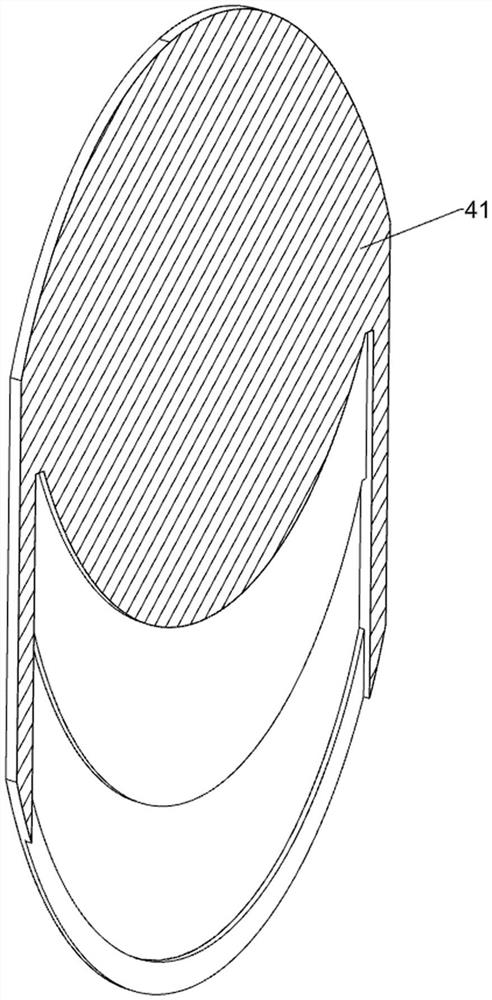
[0040] A rotary fermenter with high feeding efficiency, such as Figure 1-11 As shown, it includes a support base 1, an electric push rod 2, a first guide frame 3, a rotating shaft 4, a fermenter side wall 41, a fermenter main body 5, a screw cap 6, a stirring mechanism 7 and an extrusion discharge mechanism 8, An electric push rod 2 is fixedly installed on the support base 1, and a first guide frame 3 for guiding is symmetrically and fixedly installed on the support base 1. The first guide frame 3 is rotatably connected with a rotation shaft 4, and one end of the rotation shaft 4 is welded with a fermenter. The side wall 41 of the tank, and the side walls 41 of the two fermentation tanks are jointly fixed with the main body 5 of the fermentation tank, the top of the main body 5 of the fermentation tank is connected with a screw cap 6 through thread fit, and the end of the telescopic shaft of the electric push rod 2 is provided with a stirring mechanism 7 , the stirring mechan...
Embodiment 2
[0047] On the basis of Example 1, such as Figure 10-11 As shown, an anti-blocking mechanism 9 is also included, and the right side of the fermenter side wall 41 on the right is provided with an anti-blocking mechanism 9, and the anti-blocking mechanism 9 is used to prevent the discharge hole of the first perforated arc plate 85 from being blocked The anti-blocking mechanism 9 includes a second guide frame 91, a second perforated arc-shaped plate 92 and a sliding frame 93, and the right side of the fermenter side wall 41 on the right side is fixedly connected with the second guide frame 91 for guiding. A second perforated arc plate 92 is slidably connected to the first perforated arc plate 85, and the second perforated arc plate 92 is used to block the discharge hole of the first perforated arc plate 85, and the second perforated arc plate 92 is used to block the discharge hole of the first perforated arc plate 85. The shaped plate 92 is slidably connected with the sliding pla...
Embodiment 3
[0050] On the basis of Example 1, such as Figure 12 As shown, it also includes an aeration mechanism 10, which is arranged on the top of the fermenter main body 5, and the aeration mechanism 10 is used to add oxygen to the interior of the fermenter. The aeration mechanism 10 includes an air pump 101 and an opening rod 102, An air pump 101 is fixedly installed on the top of the fermenter main body 5, and an opening rod 102 is fixedly connected to the air pump 101. The air pump 101 is used to transport external oxygen to the main body 5 of the fermenter through the opening rod 102, and the opening rod 102 passes through the fermentation tank body 5. Tank body 5.
[0051] The staff manually starts the air pump 101, and the air pump 101 transports the external oxygen to the main body 5 of the fermenter through the opening rod 102, thereby increasing the oxygen content in the fermenter, and then the fermented product inside the fermenter can be fermented quickly, further reducing ...
PUM
 Abstract
Description
Claims
Application Information
 - R&D
- Intellectual Property
- Life Sciences
- Materials
- Tech Scout
- Unparalleled Data Quality
- Higher Quality Content
- 60% Fewer Hallucinations
Browse by: Latest US Patents, China's latest patents, Technical Efficacy Thesaurus, Application Domain, Technology Topic, Popular Technical Reports.
© 2025 PatSnap. All rights reserved.Legal|Privacy policy|Modern Slavery Act Transparency Statement|Sitemap|About US| Contact US: help@patsnap.com


