Spiral supercharged fuel oil centrifuge for vehicle

A technology of screw supercharger and centrifuge, applied in non-displacement pumps, non-variable volume pumps, machines/engines, etc., can solve the problems of insufficient oil supply, oil suction resistance, long oil suction section of the oil pump, etc., and achieve high combustion efficiency. Fully, improve the combustion efficiency, improve the effect of fuel density

Pending Publication Date: 2022-02-25
王小春
View PDF0 Cites 0 Cited by
  • Summary
  • Abstract
  • Description
  • Claims
  • Application Information

AI Technical Summary

Problems solved by technology

[0003] The electric fuel pump used for the existing fuel injection engine is installed in the oil supply pipeline, the oil pump suction section is long, and it is easy to generate air resistance, resulting in resistance when the oil is sucked. resistance, resulting in insufficient fuel supply and unstable fuel supply in the fuel system

Method used


Image

  • Spiral supercharged fuel oil centrifuge for vehicle
  • Spiral supercharged fuel oil centrifuge for vehicle
  • Spiral supercharged fuel oil centrifuge for vehicle

Examples


Embodiment 1

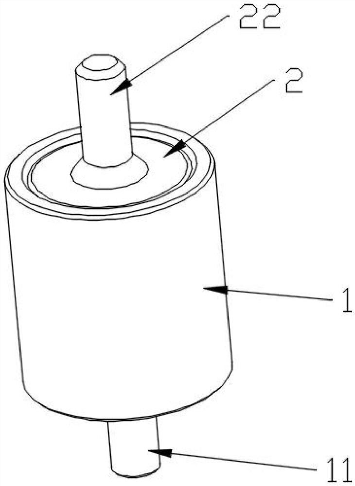
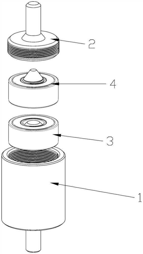
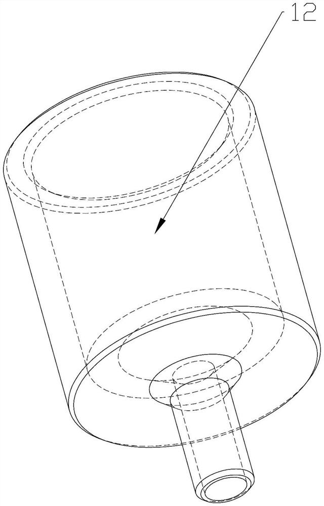
[0038] Example 1, such as Figure 1 to Figure 13 As shown, a spiral supercharged vehicle fuel centrifuge is provided with a shaft sleeve 1, the upper end of the shaft sleeve 1 is provided with a sleeve head 2, the lower end of the shaft sleeve 1 is provided with an oil inlet pipe 11, and the upper end of the sleeve head 2 is provided with an oil outlet pipe 22. 1 is provided with a circular hole groove 12, and the circular hole groove 12 is provided with an oil inlet bearing assembly 3 and an oil outlet bearing assembly 4. The assembly 4 is provided with a bearing II41, and a threaded core II42 is arranged inside the bearing II41.

[0039] The threaded core I32 is interference fit with the inner ring of the bearing I31, and the threaded core I32 rotates in the bearing I31; the threaded core II42 interferes with the inner ring of the bearing II41, and the threaded core II42 rotates with the bearing II41.

[0040] A spiral groove 5 is provided in the middle of the outer surface...

Embodiment 2

[0048] Such as Figure 14 to Figure 18 As shown, this embodiment is basically the same as Embodiment 1, except that the upper ends of the threaded core II 42 and the threaded core I 32 are changed to a helical blade-shaped platform 44, and the lower ends of the threaded core I 32 and the threaded core II 42 are cut flat.

[0049] A partition 8 is provided between the oil inlet bearing assembly 3 and the oil outlet bearing assembly 4 , and a chamfered circular groove 81 is provided in the middle of the upper and lower sides of the partition 8 .

[0050] The function of the spacer 8 is to divide the circular hole 12 in the shaft sleeve 1 into two chambers, so that the threaded core I32 and the threaded core II42 are respectively located above and below the spacer 8, and the threaded core I32 and the threaded core II42 are in the When rotating at a high speed, they will not interfere with each other, preventing the threaded core I32 from conflicting with the threaded core II42. ...


PUM


Abstract

The invention discloses a spiral supercharged fuel oil centrifuge for a vehicle. The centrifuge is provided with a shaft sleeve, a sleeve head is arranged at the upper end of the shaft sleeve, an oil inlet pipe is arranged at the lower end of the shaft sleeve, an oil outlet pipe is arranged at the upper end of the sleeve head, a round hole groove, an oil inlet bearing assembly and an oil outlet bearing assembly are arranged in the shaft sleeve, the oil inlet bearing assembly is provided with a bearing I and a threaded core I, and the oil outlet bearing assembly is provided with a bearing II and a threaded core II. According to the invention, two groups of specific sealed bearing assemblies, the shaft sleeve and the sleeve head are assembled, the shaft sleeve is provided with an oil inlet pipe and the oil outlet pipe, and the threaded cores with the spiral spiral grooves are arranged in the middles of the bearing assemblies, so that the threaded cores rotate at a high speed by virtue of suction of vacuum degree of an engine during use, and fuel enters from the oil inlet pipe and is extruded by the spiral spiral groove; and in combination with high-speed rotation of the threaded cores, great oil pressure is generated, then oil is sprayed out from the oil outlet pipe, fuel oil density is improved by squeezing the fuel oil, fuel oil combustion is efficient and sufficient, combustion efficiency is improved, and the effects of saving oil and reducing waste gas emission are achieved.

Description

technical field [0001] The invention relates to the technical field of auto parts, in particular to a screw supercharged vehicle fuel centrifuge. Background technique [0002] Fuel has become the most traditional automobile fuel and is widely used in various models. The function of the fuel pump is to suck the fuel out of the fuel tank and press it into the float chamber of the carburetor through the pipeline and fuel filter. It is thanks to the fuel pump that the fuel tank can be placed at the rear of the car away from the engine and below the engine. [0003] The electric fuel pump used for the existing fuel injection engine is installed in the oil supply pipeline, the oil pump suction section is long, and it is easy to generate air resistance, resulting in resistance when the oil is sucked. The resistance, resulting in insufficient fuel supply, unstable fuel supply to the fuel system. Contents of the invention [0004] Purpose of the invention: In order to overcome th...

Claims


Application Information

Patent Timeline
Patent Type & Authority Applications(China)
IPC IPC(8): F02M37/04F04D1/00F04D29/043F04D29/046F04D29/42
CPCF02M37/04F04D1/00F04D29/043F04D29/046F04D29/426
Inventor 王小春
Owner 王小春
Why Eureka
Try Eureka