Power waveform generator with four-quadrant feedback loop and control method thereof
A waveform generator and feedback loop technology, applied in digital function generators, sinusoidal oscillator train generators, instruments, etc., can solve the problems of complex circuit design, high noise, technical difficulties, etc.
- Summary
- Abstract
- Description
- Claims
- Application Information
AI Technical Summary
Problems solved by technology
Method used
Image
Examples
Embodiment 1
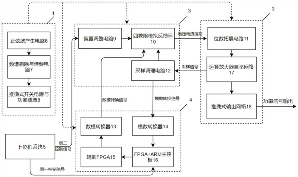
[0036] Such as figure 1As shown, a power waveform generator with a four-quadrant feedback loop includes a switching power supply module 1, a power amplification module 2, a four-quadrant feedback loop 3, a digital signal processing and control circuit 4 and a host computer system 5; the switch The power supply module 1 is connected with the power amplification module 2, the four-quadrant feedback loop 3 and the digital signal processing and control circuit 4, and supplies power to them; the four-quadrant feedback loop 3, the digital signal processing and control circuit 4 are also respectively connected with the upper computer system 5 Connection; the four-quadrant feedback loop 3 is also connected to the power amplification module 2 and the digital signal processing and control circuit 4 respectively.
[0037] The switching power supply module 1 includes a sine wave generating circuit 6 connected in sequence, a spectrum elimination and frequency multiplication circuit 7, and ...
Embodiment 2
[0056] A control method of a power waveform generator with a four-quadrant feedback loop, comprising the following steps:
[0057] S1: The sine wave generating circuit 6 generates a sine wave drive signal, and after the spectrum elimination and the superimposition signal of the frequency multiplier waveform of the drive signal generated by the frequency multiplication circuit 7, drives the push-pull switching power supply and the power filter 8 to the power amplifier module 2, The four-quadrant feedback loop 3 and the digital signal processing and control circuit 4 provide power;
[0058] S2: The upper computer system 5 is controlled by the user to output the first control signal and the second control signal respectively, wherein the first control signal is input to the FPGA+ARM main control board 16, and the parsed command is sent to the auxiliary FPGA15 as a secondary command. Further control the digital-to-analog converter 13 to generate the signal after the digital-to-ana...
PUM
 Abstract
Description
Claims
Application Information
 - R&D
- Intellectual Property
- Life Sciences
- Materials
- Tech Scout
- Unparalleled Data Quality
- Higher Quality Content
- 60% Fewer Hallucinations
Browse by: Latest US Patents, China's latest patents, Technical Efficacy Thesaurus, Application Domain, Technology Topic, Popular Technical Reports.
© 2025 PatSnap. All rights reserved.Legal|Privacy policy|Modern Slavery Act Transparency Statement|Sitemap|About US| Contact US: help@patsnap.com


