Forming die and method for high-precision thin-shell structure composite material wave-transparent antenna housing

A composite material and thin-shell structure technology, which is applied in the field of forming molds for high-precision thin-shell structure composite wave-transparent radome, can solve problems that affect the uniformity of product wall thickness, accumulative tolerance of positioning fit, and affect the electrical performance of the radome. , to achieve the effects of improving compactness and uniformity, easy operation, and eliminating cumulative tolerances

Pending Publication Date: 2022-03-01
ZHUZHOU FEILU ADVANCED MATERIAL TECH CO LTD
View PDF1 Cites 2 Cited by
  • Summary
  • Abstract
  • Description
  • Claims
  • Application Information

AI Technical Summary

Problems solved by technology

As stated in patent 201910587003.2, the inner and outer surfaces of the product produced by the mold of this structure are smooth, and only a small amount of manual polishing is required in the later stage. However, the product formed by the mold of this structure has only vertical downward pressure and no lateral pressure. The compactness of the side is poor, and the thickness of the bottom and side walls of the manufactured product is different, which affects the electrical performance of the radome; the second is that the female mold and the male mold have a positioning ring, which leads to the positioning fit between the female mold and the male mold. There are accumulated tolerances and the precision is not high, which once again affects the uniformity of the product wall thickness; the third is that this structural form designs a large number of screw connection parts in the process of mold assembly and demoulding, so the efficiency in the actual production process is not high

Method used


Image

  • Forming die and method for high-precision thin-shell structure composite material wave-transparent antenna housing
  • Forming die and method for high-precision thin-shell structure composite material wave-transparent antenna housing
  • Forming die and method for high-precision thin-shell structure composite material wave-transparent antenna housing

Examples


Embodiment 1

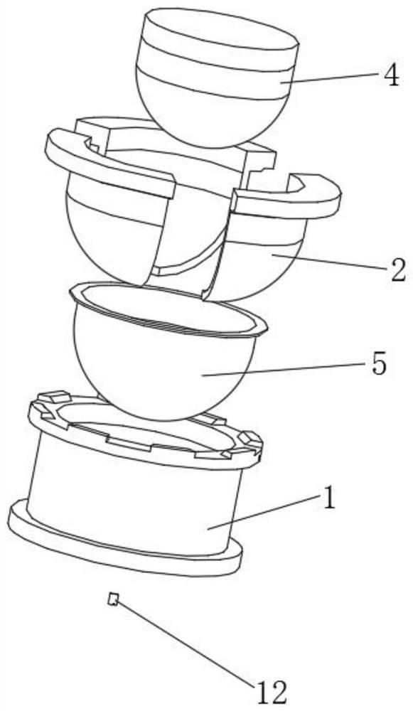
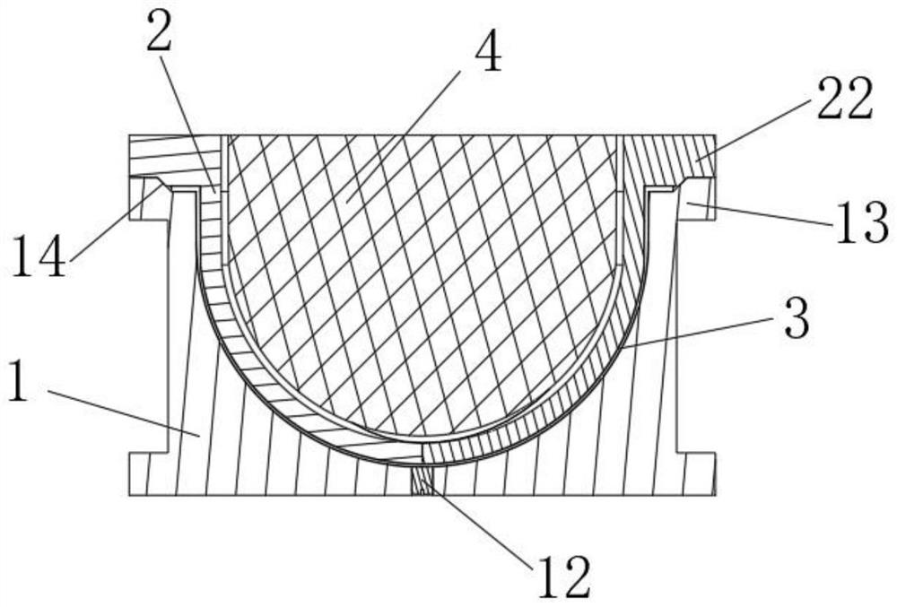
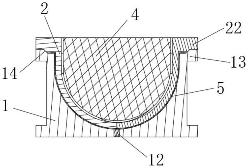
[0042] Such as Figure 1~6 As shown, the molding die of the high-precision thin-shell structure composite wave-transparent radome in this embodiment includes a female mold 1 and a male mold 2 that cooperate with each other. The molding cavity 3 of the product 5, the male mold 2 is a shell structure and is formed by a combination of multi-lobed male mold units 21, the male mold 2 is equipped with a thermal expansion mandrel 4, and the thermal expansion mandrel 4 expands after being heated to squeeze the male mold 2 .

[0043] In this embodiment, the inner surface of the female mold 1 corresponding to the molding cavity 3 is used to shape the outer surface of the radome product 5 , and the outer surface of the male mold 2 corresponding to the molding cavity 3 is used to shape the inner surface of the radome product 5 . Since the male mold 2 is designed in the form of a multi-lobe combination, and the multi-lobe male mold units 21 are independent of each other, during the moldin...

Embodiment 2

[0054] A method for forming a high-precision thin-shell structure composite wave-transparent radome, comprising the following steps:

[0055] 1) Prepare the forming mold for the wave-transparent radome of the high-precision thin-shell structure composite material in Example 1. The mold is designed so that the thickness of the formed radome is 1.84-1.90 mm.

[0056] 2) Before molding: first screw the demoulding blow plug 12 into the demoulding blowing hole 11; The slanted opening 14 is used as a benchmark, and the male mold 2 (the male mold 2 is made of aluminum alloy, and the thermal expansion coefficient of the aluminum alloy is 2.36×10 -5 / °C) is placed in the female mold 1, and then the thermal expansion mandrel 4 (the thermal expansion coefficient of silicone rubber is 5.6×10 -4 / °C) placed in the male mold 2.

[0057] The specific laying method of the composite material for the above-mentioned radome is as follows: first prepare the female mold 1, apply a release agent,...

Embodiment 3

[0068] A method for forming a high-precision thin-shell structure composite wave-transparent radome, comprising the following steps:

[0069] 1) Prepare the forming mold for the wave-transparent radome of the high-precision thin-shell structure composite material in Example 1. The mold is designed so that the thickness of the formed radome is 1.84-1.90 mm.

[0070] 2) Before forming: screw the demoulding blowing plug 12 into the demoulding blowing hole 11; then spread the composite material for the radome on the inner surface of the female mold 1 corresponding to the forming cavity 3; The oblique opening 14 of the aluminum alloy is used as a benchmark, and the aluminum alloy male mold 2 (the coefficient of thermal expansion of the aluminum alloy is 2.36×10 -5 / °C) is placed in the female mold 1, and then the thermal expansion mandrel 4 (the thermal expansion coefficient of silicone rubber is 5.6×10 -4 / °C) placed in the male mold 2.

[0071] The specific laying method of the...


PUM

PropertyMeasurementUnit
thicknessaaaaaaaaaa

Abstract

The invention provides a forming die and method for a high-precision thin-shell-structure composite material wave-transparent radome, the forming die comprises a female die and a male die which are matched with each other, a forming cavity used for forming a radome product is formed between the female die and the male die, the male die is of a shell structure and is formed by combining a plurality of male die units, and the male die units are connected with the female die and the male die. A thermal expansion core mold is arranged in the male mold in a matched mode, and the thermal expansion core mold expands after being heated and can extrude the male mold. The forming method comprises the following steps: 1) preparing a forming mold; 2) paving a composite material for the antenna housing on the inner surface of the female die corresponding to the forming cavity; placing the male die in the female die, and placing the thermal expansion core die in the male die; 3) heating, pressurizing and curing; 4) cooling and taking out; and taking out the thermal expansion core mold and demolding. The male die formed by combining the multiple male die units is arranged, and the thermal expansion core die is combined to increase the die assembly auxiliary pressure, so that the compactness and the uniformity of an antenna housing product can be effectively improved.

Description

technical field [0001] The invention belongs to the technical field of forming dies for radome, and in particular relates to a forming die and method for a high-precision thin-shell structure composite material wave-transmitting radome. Background technique [0002] A radome is a component that protects an antenna system from the external environment. It has good wave-transmitting performance in terms of electrical performance, and the wave-transmitting performance of the radome has a great relationship with the material, thickness uniformity, and compactness of the product. [0003] In the prior art, there are generally two types of radome making: one is the vacuum bag pressing method, which uses a single mold (usually a positive mold), supplemented by vacuum bag pressing, and then puts it into an oven for curing and molding. The mold structure of this molding method is simple, but the outer surface of the product made by vacuum bag pressing will appear uneven, and a large...

Claims


Application Information

Patent Timeline
Patent Type & Authority Applications(China)
IPC IPC(8): B29C70/34B29C70/54B29C33/10B29C33/30B29C33/38B29C35/02
CPCB29C70/345B29C70/54B29C33/10B29C33/305B29C33/38B29C35/02
Inventor 杨润田黄立志刘佳娜郭海涛
Owner ZHUZHOU FEILU ADVANCED MATERIAL TECH CO LTD
Why Eureka
Try Eureka