
X-ray equipment and scattering correction method applied to X-ray equipment

A scattering correction and X-ray technology, applied in the medical field, can solve the problems of many production process and precision requirements, increasing the overall cost of the CT system, and ASG deviating from the ideal state, etc., to achieve the effect of increasing the distribution range, increasing the cost, and reducing the dependence.

Pending Publication Date: 2022-03-01
SHANGHAI UNITED IMAGING HEALTHCARE
View PDF5 Cites 0 Cited by
  • Summary
  • Abstract
  • Description
  • Claims
  • Application Information

AI Technical Summary

Problems solved by technology

However, since the ASG is on the optical path between the X-ray source and the ray-receiving end of the detector, the main ray is easy to introduce additional error information. Among them, the ASG deviates from the ideal state due to factors such as the design of the ASG itself, processing errors, or the environment, resulting in Problem with poor image quality
In addition, because ASG itself is difficult to process, it requires a lot of production technology and precision, resulting in high cost, which increases the overall cost of the CT system

Method used


Image

  • X-ray equipment and scattering correction method applied to X-ray equipment
  • X-ray equipment and scattering correction method applied to X-ray equipment
  • X-ray equipment and scattering correction method applied to X-ray equipment

Examples


Embodiment Construction

[0026] An X-ray device of the present invention and a scattering correction method applied to the X-ray device will be further described in detail below, wherein a preferred embodiment of the present invention is shown, and it should be understood that those skilled in the art can modify the present invention described herein. invention while still realizing the beneficial effects of the present invention. Therefore, the following description should be understood as the broad knowledge of those skilled in the art, but not as a limitation of the present invention.

[0027] In order to more clearly illustrate the technical solutions of the embodiments of the present application, the following briefly introduces the drawings that need to be used in the description of the embodiments. However, it will be apparent to those skilled in the art that the present application may be practiced without these details. In other instances, well-known methods, procedures, systems, components,...


PUM


Abstract

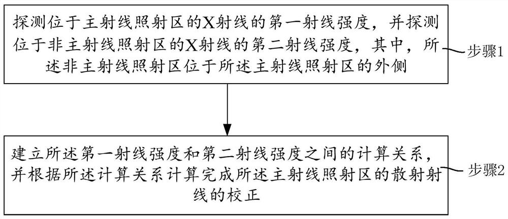
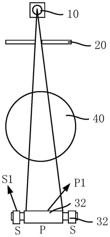
The invention provides an X-ray device and a scatter correction method applied to the X-ray device, and the scatter correction method comprises the steps: detecting the first ray intensity of an X-ray located in a main ray irradiation region, and detecting the second ray intensity of an X-ray located in a non-main ray irradiation region, the non-main ray irradiation area is positioned on the outer side of the main ray irradiation area; the calculation relation between the first ray intensity and the second ray intensity is established, and the correction of the scattered rays of the main ray irradiation area is calculated according to the calculation relation, so that the influence of the scattered rays on the main rays can be effectively weakened, the dependence of the scattered rays on an anti-scattering grating is reduced, and the anti-scattering effect of the main rays is improved. Compared with the prior art, a detector is not additionally arranged in a large range to enlarge the distribution range of the detector, the cost of the detector is not obviously increased, and the dependence of the scattering correction method on hardware correction is reduced, so that the scattering correction difficulty is reduced.

Description

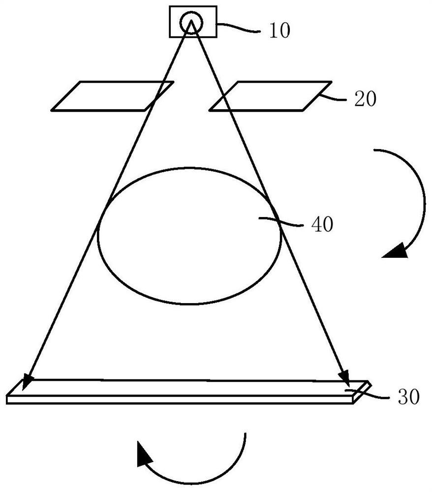
technical field [0001] The invention relates to the field of medical technology, in particular to an X-ray device and a scattering correction method applied to the X-ray device. Background technique [0002] As a medical device with high image resolution, fast imaging speed, powerful post-processing function and low radiation dose, X-ray equipment is widely used in the field of medical diagnosis and treatment. The X-ray equipment includes an X-ray source and a detector arranged oppositely, and an object to be scanned is arranged between the X-ray source and the detector. When the X-ray source irradiates the scanning object, two physical processes occur, namely the photoelectric effect and the Compton effect. Taking the CT system as an example, during image reconstruction, the scattered photons generated by the Compton effect will greatly interfere with image reconstruction, and the ratio of the intensity of the scattered rays to the intensity of the main rays will also vary...

Claims


Application Information

Patent Timeline
Patent Type & Authority Applications(China)
IPC IPC(8): G01N23/20G01N23/20008
CPCG01N23/20G01N2223/051G01N2223/1016
Inventor 杨鹏
Owner SHANGHAI UNITED IMAGING HEALTHCARE
Learn More