
Method for manufacturing heat exchanging tube of heat exchanger

A manufacturing method and heat exchanger technology, applied to heat exchange equipment, indirect heat exchangers, tubular elements, etc., can solve problems such as difficult welding, difficult control of gaps, and reduced heat exchange efficiency, so as to eliminate false welding and assembly work Efficiency improvement, effect of improving heat exchange efficiency and product quality

Inactive Publication Date: 2004-03-10
张书贵
View PDF0 Cites 0 Cited by
  • Summary
  • Abstract
  • Description
  • Claims
  • Application Information

AI Technical Summary

Problems solved by technology

The heat exchange tubes produced by the above manufacturing method have the following disadvantages: First, the gap between the outer surface of the finned tube and the inner tube wall of the outer tube is difficult to control, and if the gap is too small, it is difficult to assemble and even cannot be assembled. Work efficiency; if the gap is too large, it is not easy to weld, which not only reduces the heat exchange efficiency, but also the finned tube is easy to fall off and shortens the service life of the heat exchanger; The solder will flow downward due to the action of gravity, resulting in uneven soldering of the joint surface between the fin tube and the outer tube, and even virtual soldering, which greatly reduces the heat transfer efficiency and product quality

Method used


Image

  • Method for manufacturing heat exchanging tube of heat exchanger
  • Method for manufacturing heat exchanging tube of heat exchanger
  • Method for manufacturing heat exchanging tube of heat exchanger

Examples


Embodiment Construction

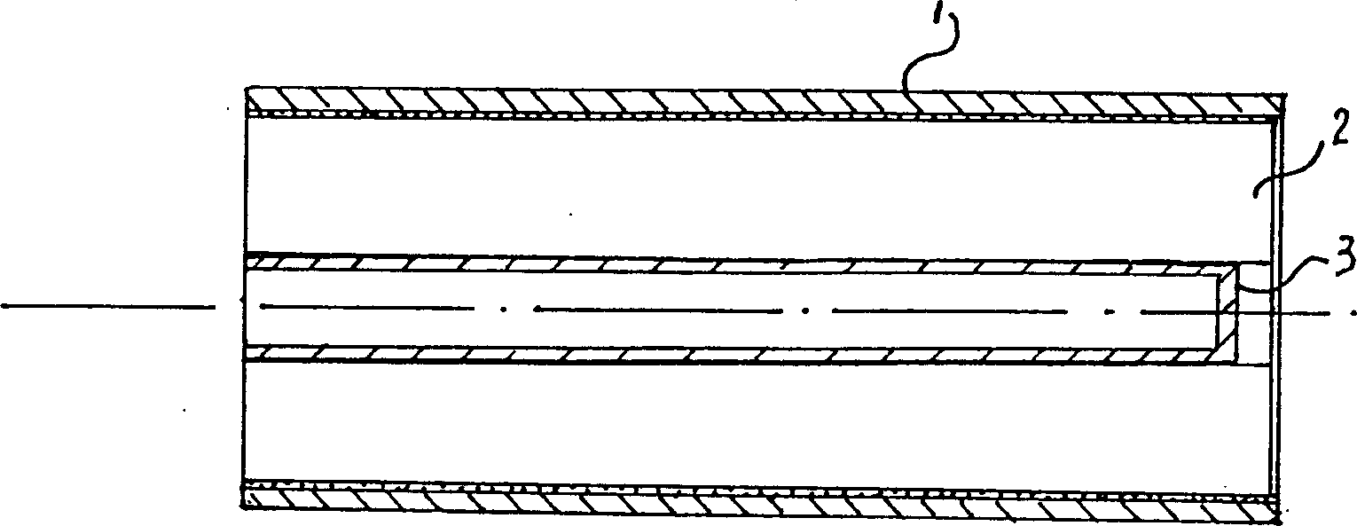
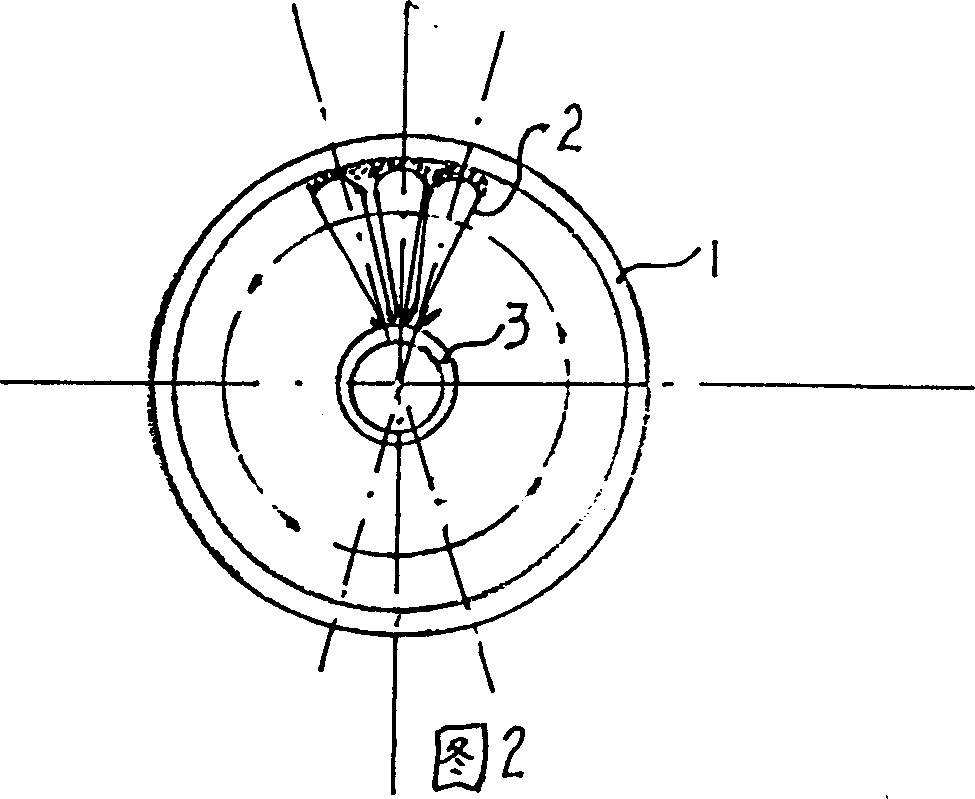
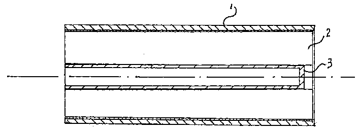
[0011] As shown in the figure, the manufacturing method of the present invention includes the following steps: (a), cutting the outer tube 1, the fin tube 2 and the core tube 3; (b), penetrating the core tube 3 into the wing (c), the outer surface of the finned tube 2 is hung with solder and then fitted into the lumen of the outer tube 1 in a dynamic fit manner; (d), the outer tube 1 end is pre-shrunk for a length and penetrates into the shrinking mold, and the inner diameter of the shrinking mold is set to be smaller than the outer diameter of the outer tube 1 by 1 mm; (e), one end of the outer tube 1 is placed in a lathe chuck for clamping, and the other One end is tightened with the head of the tailstock of the lathe, and corrected so that the axes of the chuck, the outer tube 1 and the head coincide, and the shrink film is fixed on the large carriage of the lathe; (f), the lathe is opened, and the drive chuck The disk drives the outer tube 1 to rotate, and the moving of th...


PUM


Abstract

A method for making heat exchanging tube of heat exchanger includes cutting to obtain external tube, finned tube and core tube, welding the core tube in the finned tube, applying tin on the surface of finned tube, inserting it in external tube, reducing the diameter of end part of external tube, inserting it in a pipe reducing die, clamping one end of external tube by the chuck of machine-tool, pushing its another end by a pusher, and rotating the external tube which moving said pipe reducing die from one end to another end. Its advantages are high heat exchanging efficiency and high quality of product.

Description

Technical field: [0001] The invention relates to a heat exchanger, in particular to a method for manufacturing a heat exchange tube for the heat exchanger. Background technique: [0002] Heat exchangers are widely used in air compressors and heat exchange equipment. There are many structures of heat exchange tubes in heat exchangers. One type of heat exchange tube has a finned tube with a core tube in the inner cavity of an outer tube. The current manufacturing method of the heat exchange tube is: cutting The outer tube, the finned tube and the core tube; the core tube is penetrated into the lumen of the finned tube and fixed by welding; the outer surface of the finned tube is hung with solder and installed on the outer tube by means of top loading In the lumen of the tube; heat the assembled heat exchange tube in a heating furnace to melt the solder, weld the outer surface of the finned tube to the inner tube wall of the outer tube, and then cool. The heat exchange tubes ...

Claims


Application Information

Patent Timeline
Patent Type & Authority Patents(China)
IPC IPC(8): B21D53/02F28D15/02F28F1/10
Inventor 张书贵张朝阳
Owner 张书贵
Learn More