
Circularly polarized microstrip phased-array antenna with broadband wide-angle scanning

A phased array antenna, wide-angle scanning technology, applied in the directions of individually powered antenna arrays, antennas, antenna arrays, etc., can solve problems such as working bandwidth limitation applications

Inactive Publication Date: 2022-03-01
FUDAN UNIV
View PDF4 Cites 2 Cited by
  • Summary
  • Abstract
  • Description
  • Claims
  • Application Information

AI Technical Summary

Problems solved by technology

However, the microstrip antenna is a high-Q resonant antenna, and its narrow working bandwidth limits further applications

Method used


Image

  • Circularly polarized microstrip phased-array antenna with broadband wide-angle scanning
  • Circularly polarized microstrip phased-array antenna with broadband wide-angle scanning
  • Circularly polarized microstrip phased-array antenna with broadband wide-angle scanning

Examples


Embodiment Construction

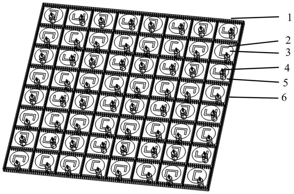
[0020] The antenna adopts a "metal-dielectric-metal" sandwich structure. Firstly, the upper metal copper foil patch 3 with a thickness of 18-35 microns is printed on the microwave dielectric board 5 by PCB technology, and the U groove 2 is opened on the patch 3. The line width of the groove should be 1-2 mm wide, and the depth should be 18-35 microns deep. The length and width of the U-slit are both smaller than the diameter of the circular patch. The specific size is determined according to the impedance and axial ratio bandwidth required by the actual antenna. and then open a thin cylindrical hole with a diameter of 1.3 mm at the feed position of the dielectric plate. A metal floor 6 is then attached below the dielectric board 5 . Finally, use a coaxial probe to insert into the medium and connect to the upper metal patch 1.

[0021] figure 1 Oblique view of a circularly polarized microstrip phased array antenna scanned angularly for a wide bandwidth.

[0022] figure 2 T...


PUM

PropertyMeasurementUnit
thicknessaaaaaaaaaa
thicknessaaaaaaaaaa
diameteraaaaaaaaaa

Abstract

The invention belongs to the technical field of antennas, and particularly relates to a broadband wide-angle scanning circularly polarized microstrip phased-array antenna. The antenna comprises three parts, namely an upper copper foil metal patch, a middle microwave dielectric layer and a lower metal floor, the metal patch is circular, and asymmetric U-shaped grooves are formed in the metal patch; and the coaxial feed probe is inserted into the circular holes in the dielectric plate and the floor and is directly connected with the upper-layer metal patch to excite the antenna. The introduction of the asymmetric U-shaped groove can effectively adjust the characteristics of TM10, TM01 and slot modes of the patch antenna, can increase the length of a current path, and is beneficial to miniaturization. When the three orthogonal modes are excited at the same time, the circularly polarized microstrip phased-array antenna with the broadband characteristic can be realized. Periodic metalized through holes are formed in the dielectric layer, the diameter of the through holes is 0.3 mm, the distance between the through holes is 0.5 mm, and the periodic metalized through holes are used for restraining surface wave propagation and achieving wide-angle scanning of the phased array.

Description

technical field [0001] The invention belongs to the technical field of antennas, in particular to a circularly polarized microstrip phased array antenna with wide bandwidth and angular scanning. Background technique [0002] With the development and wide application of satellite communication, remote sensing and telemetry, radar and other technologies, the application of circularly polarized phased array antennas is increasing. Compared with linearly polarized antennas, circularly polarized antennas can eliminate the polarization distortion loss caused by the ionospheric Faraday rotation effect, and can adapt to the reception of signals on violently swinging or rolling carriers. Microstrip antennas are widely used due to their advantages such as low profile, easy to conform to the carrier, and easy to achieve circular polarization. However, the microstrip antenna is a high-Q resonant antenna, and its narrow working bandwidth limits its further application. Wireless communi...

Claims


Application Information

Patent Timeline
Patent Type & Authority Applications(China)
IPC IPC(8): H01Q1/38H01Q1/48H01Q1/50H01Q15/24H01Q19/10H01Q21/06H01Q25/04
CPCH01Q1/38H01Q1/48H01Q1/50H01Q15/24H01Q21/065H01Q25/04H01Q19/104H01Q21/0006
Inventor 曾建平黄浩张喆关放刘晓晗资剑
Owner FUDAN UNIV
Learn More