Preparation method of hollow grid structure wing rudder

A grid structure, wing rudder technology, applied in the direction of offensive equipment, projectiles, weapon types, etc., can solve the problems of poor wing rudder performance and complex process, and achieve the effects of high forming efficiency, simple steps, and low implementation difficulty.

Pending Publication Date: 2022-03-04
BEIJING XINGHANG MECHANICAL ELECTRICAL EQUIP
View PDF8 Cites 0 Cited by
  • Summary
  • Abstract
  • Description
  • Claims
  • Application Information

AI Technical Summary

Problems solved by technology

[0005] In view of the above analysis, the embodiment of the present invention aims to provide a method for preparing a hollow grid structure wing rudder, which is used to solve the problems that the existing method for preparing a hollow grid structure wing rudder has complex processes and poor performance of the prepared wing rudder

Method used


Image

  • Preparation method of hollow grid structure wing rudder
  • Preparation method of hollow grid structure wing rudder
  • Preparation method of hollow grid structure wing rudder

Examples


preparation example Construction

[0040] The invention provides a method for preparing a wing rudder with a hollow grid structure, the preparation method comprising:

[0041] a. According to the wing rudder structure, the wing rudder is divided into two symmetrical parts up and down along the chord plane, and the upper grid plate model and the lower grid plate model are designed;

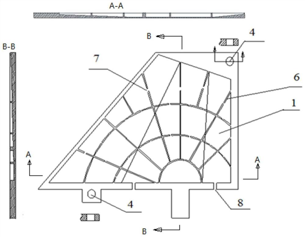
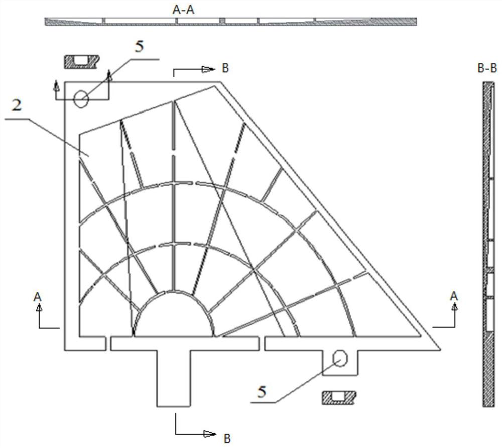
[0042] b. According to the design model, prepare the upper grid plate 1 and the lower grid plate 2, such as Figure 1-2 shown;

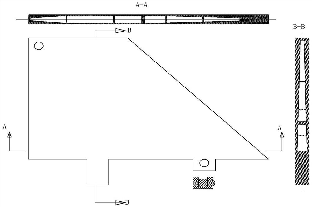
[0043] c. After assembling the upper grid plate 1 and the lower grid plate 2, carry out diffusion connection, such as image 3 and Figure 5 shown.

[0044] It should be noted that, in the present invention, the chord plane refers to the middle plane between the upper plane and the lower plane of the wing rudder, that is, Figure 7 The C-C side in . The hollow grid structure refers to a structure formed by interlacing reinforcing ribs inside the rudder, and there is no particular limitation on this st...

Embodiment 1

[0076] a. According to the wing rudder structure (chord length 500mm, span length 400mm, maximum thickness t at the root 1 = 32mm, rib width 1.5mm, material is Ti2AlNb), the rib includes a notch with a depth of 0.5mm and a width of 1.5mm, the notch is located in the middle of the rib, and the wing rudder is divided into two symmetrical parts up and down along the chord plane , to design the upper grid plate model and the lower grid plate model;

[0077] b. Prepare the upper grid plate and the lower grid plate by mechanical processing according to the design model, the thickness is 17mm (α is 2), the diameter of the guide hole of the upper grid plate and the lower grid plate is 20mm, and the blind hole of the lower grid plate 12mm deep;

[0078] Machining prepares guide post (material is Ti2AlNb), and guide post is long 25mm, and the diameter of guide post is 20mm;

[0079] The gaps on the ribs of the upper and lower grid plates are distributed in the middle of the ribs, with...

Embodiment 2

[0087] a. According to the wing rudder structure (chord length 450mm, span length 400mm, maximum thickness t at the root 1 = 40mm, rib width 1.2mm, material is Ti2AlNb), divide the wing rudder into two symmetrical parts up and down along the chord plane, and design the upper grid plate model and the lower grid plate model;

[0088] b. Prepare the upper grid plate and the lower grid plate by mechanical processing according to the design model, the thickness is 22mm (α is 4), the diameter of the guide hole of the upper grid plate and the lower grid plate is 25mm, and the blind hole of the lower grid plate 15mm deep;

[0089] The guide post (material is Ti2AlNb) is prepared by machining. The length of the guide post is 35mm, and the diameter of the guide post is 25mm. The negative difference is taken during processing, and the maximum negative difference is -0.5.

[0090] The gaps on the reinforcing ribs of the upper and lower grid plates are 0.7mm deep and 2mm wide; the opening...


PUM


Abstract

The invention relates to a preparation method of a hollow grid structure wing rudder, belongs to the technical field of preparation of wing rudders, and solves the problems that a method for preparing a wing rudder in the prior art is complex in process and the prepared wing rudder is poor in performance. The preparation method comprises the following steps: a, according to the structure of the wing rudder, dividing the wing rudder into two parts which are symmetrical up and down along a chord plane, and designing an upper grid plate model and a lower grid plate model; b, preparing an upper grid plate and a lower grid plate according to the design model; and c, assembling the upper grid plate and the lower grid plate, and performing diffusion bonding. The method is simple in step and low in implementation difficulty, and the formed wing rudder is good in performance and high in precision.

Description

technical field [0001] The invention relates to the technical field of wing rudder preparation, in particular to a preparation method of a hollow grid structure wing rudder. Background technique [0002] With the development of aircraft towards high speed, long range, and strong penetration, it is more and more urgent to reduce the weight of its main structure. Lightweight structure is nothing more than the lightest material, the most optimized structure and the most simplified connection form. The weight of the material is determined by its own density. Under the premise of satisfying the service performance, low density is the basic principle of material selection. Among the existing metal lightweight structural materials, magnesium, aluminum, and titanium alloys are commonly used structural materials. The high temperature resistance of the material itself (≥ 500°C), only titanium alloys have high temperature resistance properties. Structural optimization is determined b...

Claims


Application Information

Patent Timeline
Patent Type & Authority Applications(China)
IPC IPC(8): F42B10/02
CPCF42B10/02
Inventor 王斌李升梁滨申红斌刘太盈周福见马向宇
Owner BEIJING XINGHANG MECHANICAL ELECTRICAL EQUIP
Why Eureka
Try Eureka