Low-cost green light phase range finder

A phase ranging, low-cost technology, applied in instruments, measuring devices, radio wave measurement systems, etc., can solve the problems of unfavorable popularization, errors in ranging results, and high manufacturing costs of phase ranging instruments, and can prevent temperature drift, The effect of reducing measurement error and improving accuracy

Pending Publication Date: 2022-03-04
杭州隆硕科技有限公司
View PDF1 Cites 0 Cited by
  • Summary
  • Abstract
  • Description
  • Claims
  • Application Information

AI Technical Summary

Problems solved by technology

[0004] The existing green laser diode has a certain phase delay to the signal modulated on it, and the phase delay is different at different temperatures, which will cause errors in the ranging results of the...

Method used


Image

  • Low-cost green light phase range finder
  • Low-cost green light phase range finder

Examples


Embodiment Construction

[0032] In order to enable those skilled in the art to better understand the technical solutions of the present invention, the present invention will be further described in detail below in conjunction with the accompanying drawings.

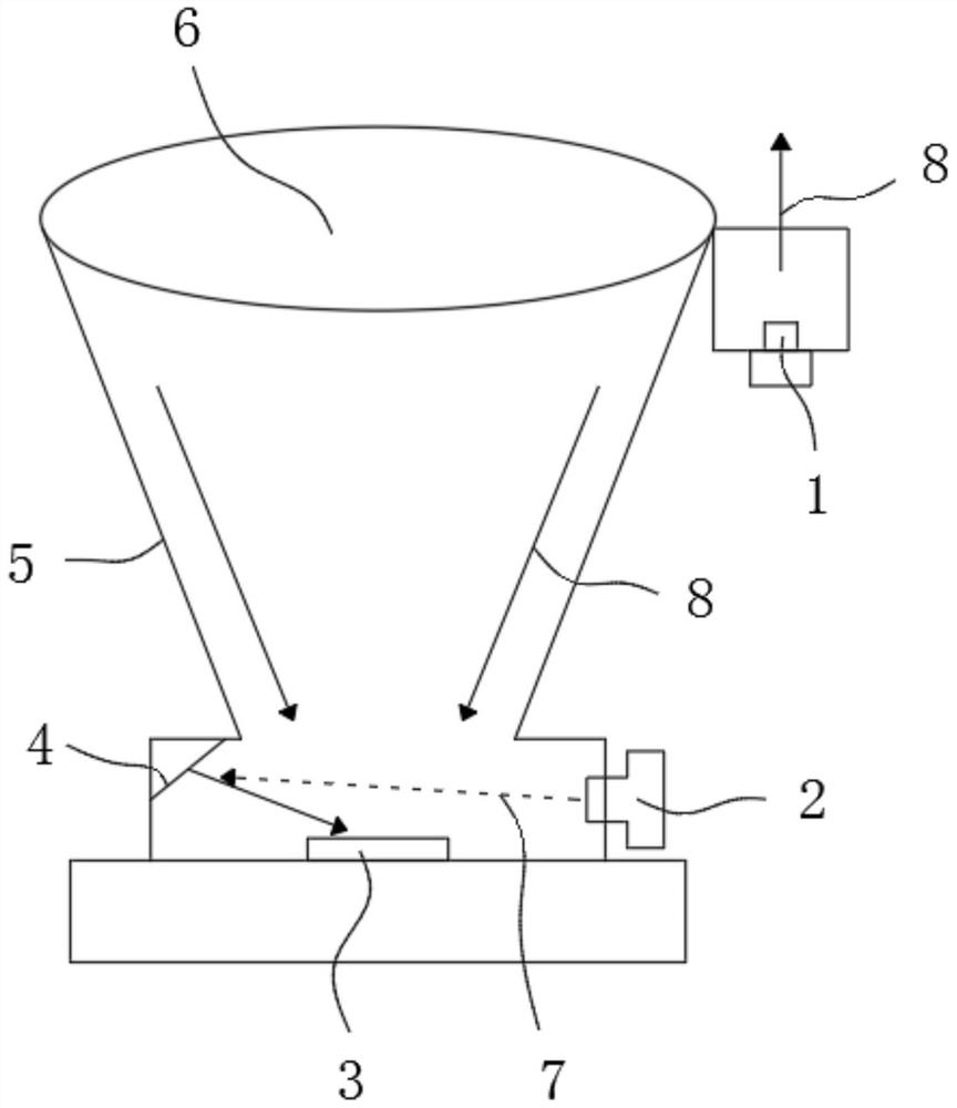
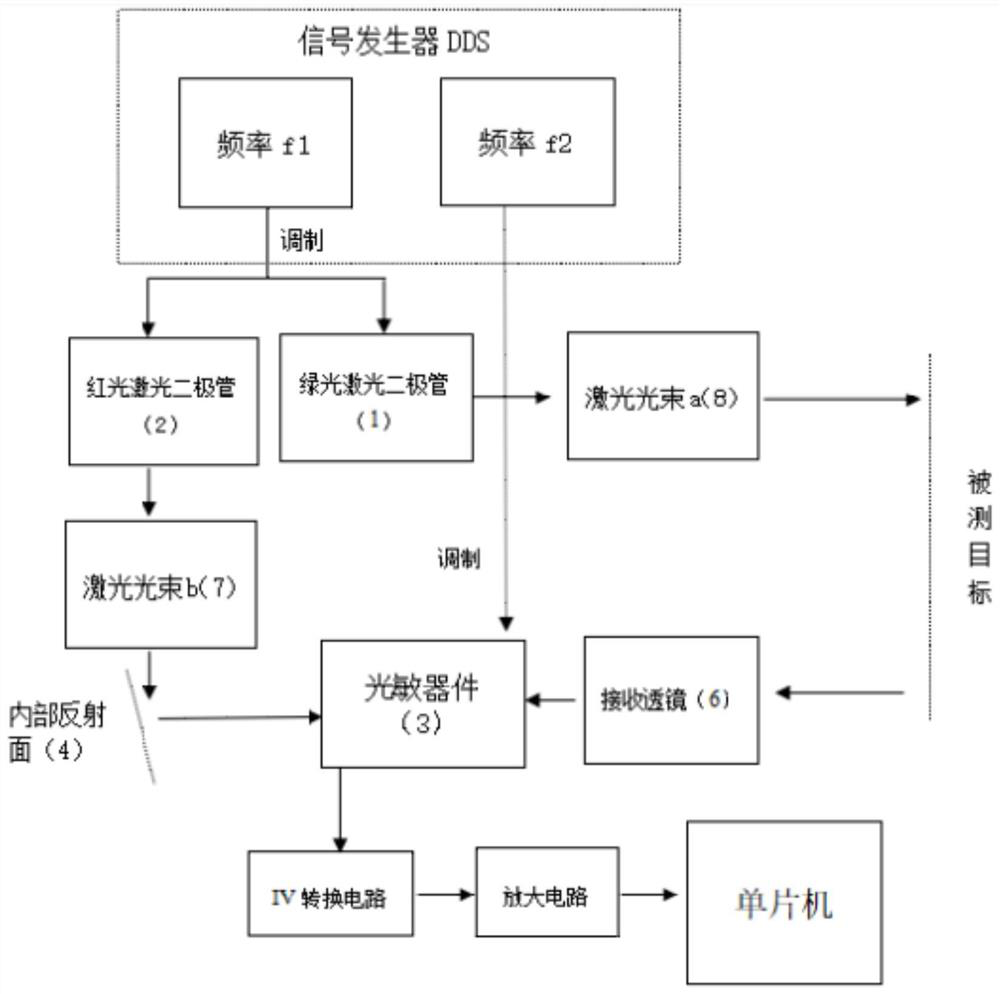
[0033] Such as figure 1 and figure 2 As shown, a low-cost green light phase range finder, including the optical machine body 5:

[0034] A green laser diode 1 and a red laser diode 2 are respectively arranged in the optical machine body 5;

[0035] The inner wall of the optical machine body 5 is provided with an internal reflection surface 4, and the internal reflection surface 4 reflects the red laser diode 2 onto the photosensitive device 3;

[0036] The open end of the optical engine body 5 is provided with a receiving lens 6 .

[0037] The green laser diode 1 emits a laser beam a8 and illuminates the target to be measured.

[0038] The red laser diode 2 emits a laser beam b7 and irradiates the internal reflection surface 4 .

[0039] Th...


PUM


Abstract

A low-cost green light phase range finder disclosed by the present invention comprises a light machine body, a green light laser diode and a red light laser diode are arranged in the light machine body, an internal reflection surface is arranged on the inner wall of the light machine body, and the internal reflection surface reflects the red light laser diode to a photosensitive device. The open end of the ray machine body is provided with a receiving lens. According to the range finder, the structural design of the green laser diode, the red laser diode and the photosensitive device is adopted, so that the manufacturing cost of the range finder is reduced while efficient and accurate range finding of the range finder is ensured, errors caused by temperature changes can be eliminated, the temperature drift phenomenon is prevented, and the range finder is suitable for large-scale popularization and application. The measurement error is reduced, and the measurement precision is improved.

Description

technical field [0001] The invention relates to the technical field of laser ranging, in particular to a low-cost green light phase ranging instrument. Background technique [0002] The green light phase laser rangefinder measures the phase delay generated by the round-trip distance of continuous modulated light waves, and indirectly measures the flight time between the light in the air and the target to be measured, so as to calculate the measured distance. The implementation method is: The high-frequency signal f1 is modulated on the semiconductor green laser tube, so that the green laser tube produces continuous high-frequency light and dark laser light, and the high-frequency signal f2 is modulated on the photodiode. After the photodiode receives the laser reflected back from the measured target , the low-frequency signal f1-f2 is obtained after mixing and filtering by the photodiode, and the measured distance is calculated by calculating the phase of the low-frequency s...

Claims


Application Information

Patent Timeline
IPC IPC(8): G01S17/32G01S7/4911G01S7/4915
CPCG01S17/32G01S7/4911G01S7/4915
Inventor 董凯龚志
Owner 杭州隆硕科技有限公司
Why Eureka
Try Eureka