Eureka AIR delivers breakthrough ideas for toughest innovation challenges, trusted by R&D personnel around the world.

Wide-range low-jitter high-precision clock signal proportion stabilizer circuit and adjusting method

A high-precision clock and clock signal technology, applied in the direction of transforming continuous pulse chains into pulse chain devices with required modes, pulse shaping, etc., can solve problems such as conversion rate and signal-to-noise ratio reduction

Active Publication Date: 2022-03-08
BEIJING MXTRONICS CORP +1
View PDF3 Cites 0 Cited by
  • Summary
  • Abstract
  • Description
  • Claims
  • Application Information

AI Technical Summary

Problems solved by technology

The circuit has a wide calibration range and can adjust the clock signal of 20%-80% clock duty cycle. The calibration output clock signal has high precision and low jitter characteristics, which improves the dynamic performance of the converter and solves the conversion rate caused by clock jitter. and the problem of degraded signal-to-noise ratio

Method used


Image

  • Wide-range low-jitter high-precision clock signal proportion stabilizer circuit and adjusting method
  • Wide-range low-jitter high-precision clock signal proportion stabilizer circuit and adjusting method
  • Wide-range low-jitter high-precision clock signal proportion stabilizer circuit and adjusting method

Examples


Embodiment 1

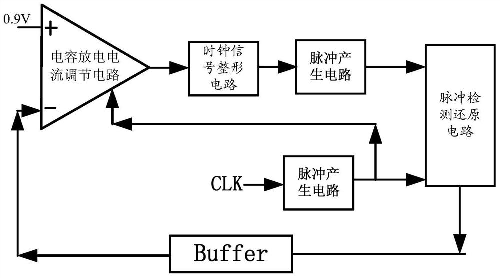
[0062] The overall structure diagram of the circuit structure of the present invention is as follows figure 1 As shown, the circuit includes a pulse signal generation circuit, a pulse signal detection and recovery circuit, a buffer module, a capacitor discharge current adjustment circuit, and a clock signal shaping circuit.

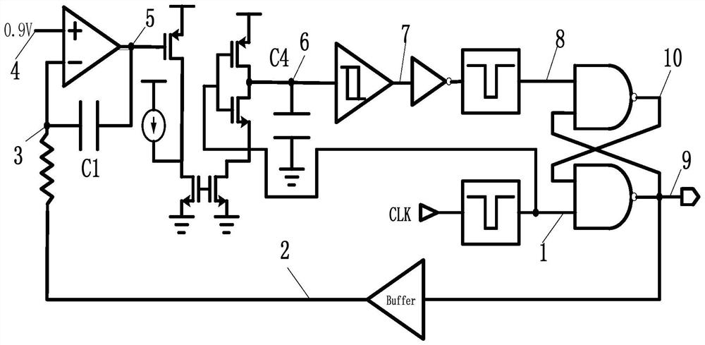
[0063] In this embodiment, the first pulse signal generating circuit and the second pulse signal generating circuit included in the clock signal shaping circuit are respectively used to receive the original clock signal and the preliminarily shaped square wave signal, and generate corresponding narrow pulse signals to enter to the pulse detection recovery circuit.

[0064] Such as figure 2As shown, after the two narrow pulse signals enter the pulse detection and restoration circuit, the detection and restoration circuit will restore the clock signal and enter the capacitor discharge current adjustment circuit through the buffer module for further adjust...


PUM


Abstract

The invention discloses a wide-range low-jitter high-precision clock signal ratio stabilizer circuit, which is characterized in that an original clock signal generates a narrow pulse signal with a corresponding duty ratio through a pulse generation circuit, one path of the narrow pulse signal enters a capacitor discharge current regulation circuit, and the other path of the narrow pulse signal enters a pulse detection and reduction circuit; the two narrow pulse signals generate reduction square waves through the pulse detection reduction circuit, the reduction square waves enter the capacitor discharge current adjusting circuit, the descending slope of triangular wave signals output by an inverter is adjusted, the triangular wave signals enter the clock signal shaping circuit, and then the phases of the narrow pulse signals are adjusted. And finally, the two narrow pulse signals pass through a pulse detection and reduction circuit to generate reduction square waves with the duty ratio of 1: 1. The circuit well solves the problem of duty ratio of an input clock, and provides an accurate clock signal for a core circuit of the converter. The invention also provides a clock signal adjusting method realized by adopting the wide-calibration-range low-jitter high-precision clock signal proportion stabilizer circuit.

Description

technical field [0001] The invention relates to a wide calibration range low-jitter high-precision clock ratio stabilizer circuit, which belongs to the technical field of analog-to-digital converters. Background technique [0002] The converter is a key component of the interface between the analog system and the digital system, and is widely used in industry, communication, radar and other fields. In recent years, the high-speed development of converters has led to the continuous improvement of the sampling rate requirements. In ultra-high-speed converters, most converter circuits use multi-channel time interleaving technology to improve the sampling rate of the overall circuit. Multi-channel time interleaving technology must Signal sampling and digital-to-analog conversion are carried out in strict accordance with the time sequence, so strict requirements are placed on the clock circuit. With the improvement of manufacturing process technology, the proportion of clock ris...

Claims


Application Information

Patent Timeline
Patent Type & Authority Applications(China)
IPC IPC(8): H03K5/156H03K5/04
CPCH03K5/156H03K5/04
Inventor 孙丹纪亚飞黄策策杨鑫
Owner BEIJING MXTRONICS CORP
Why Eureka
Eureka Blog
Learn More