
Large-outer-diameter narrow-runner impeller mold and impeller manufacturing method

A manufacturing method and large outer diameter technology, applied in the direction of manufacturing tools, casting molding equipment, casting molds, etc., can solve the problems of sand mold deformation, unreasonable distribution of position and size, easy formation of iron, etc.

Pending Publication Date: 2022-03-15
EBARA GREAT PUMPS
View PDF0 Cites 0 Cited by
  • Summary
  • Abstract
  • Description
  • Claims
  • Application Information

AI Technical Summary

Problems solved by technology

[0002] The circulating pump used in the adsorption separation process of the petrochemical PX unit usually requires a centrifugal pump with high head and low cavitation performance. In order to meet the requirements of high head and low cavitation performance of the impeller, such as Figure 4 The shown impeller structure includes blades 22, hub 24, upper cover plate 20, lower cover plate 21, and flow channel 23 formed by upper cover plate 20, lower cover plate 21 and blades 22. This type of impeller is usually designed with a large outer diameter 1. The narrow channel structure is the impeller with large outer diameter and narrow channel. Due to the narrow channel and large diameter of this type of impeller, the core is easy to deform. At the same time, the air holes on the impeller mold are directly poked by workers with tools during casting. The unreasonable size distribution of the position and the uneven air permeability of the sand mold can also easily lead to deformation of the sand mold. The comprehensive superposition of unfavorable factors makes the core easy to change during casting processing, resulting in serious deformation of the casting after molding, and there is also easy formation of iron in the interior, etc. Problem, casting scrap rate is high

Method used


Image

  • Large-outer-diameter narrow-runner impeller mold and impeller manufacturing method
  • Large-outer-diameter narrow-runner impeller mold and impeller manufacturing method
  • Large-outer-diameter narrow-runner impeller mold and impeller manufacturing method

Examples


Embodiment Construction

[0031] The following will clearly and completely describe the technical solutions in the embodiments of the present invention with reference to the accompanying drawings in the embodiments of the present invention. Obviously, the described embodiments are only some, not all, embodiments of the present invention. Based on the embodiments of the present invention, all other embodiments obtained by persons of ordinary skill in the art without making creative efforts belong to the protection scope of the present invention.

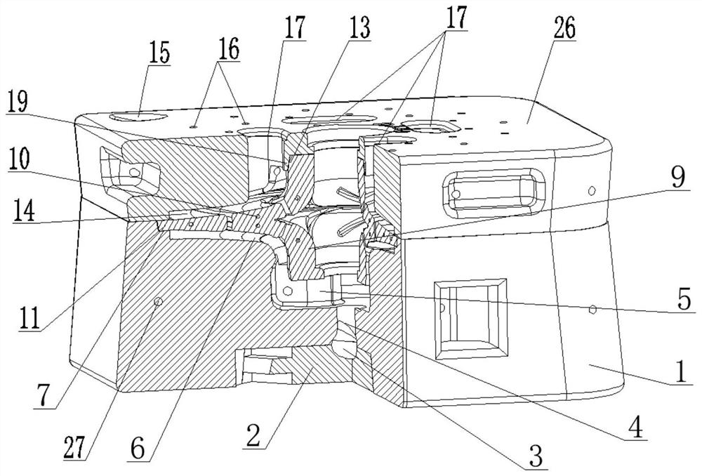
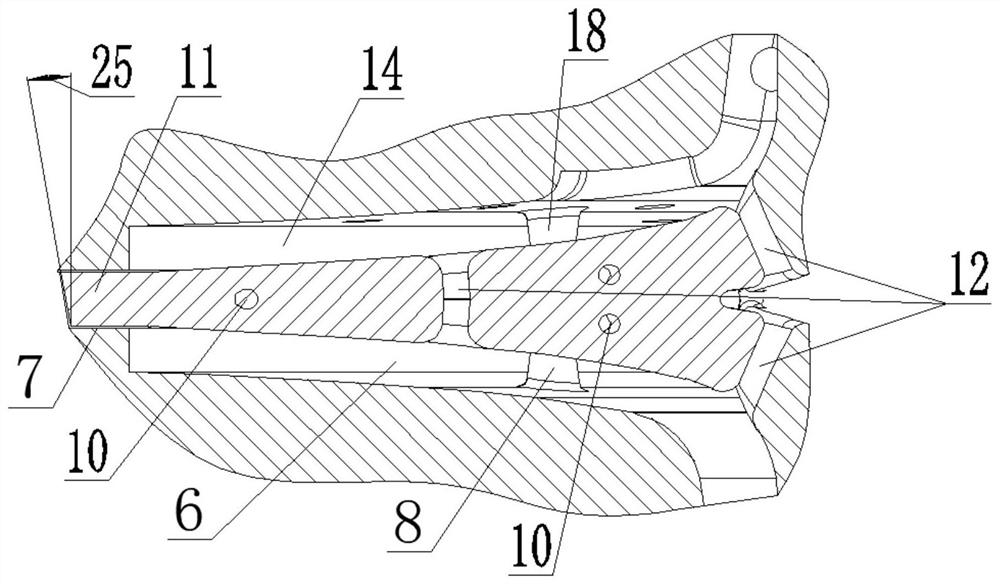
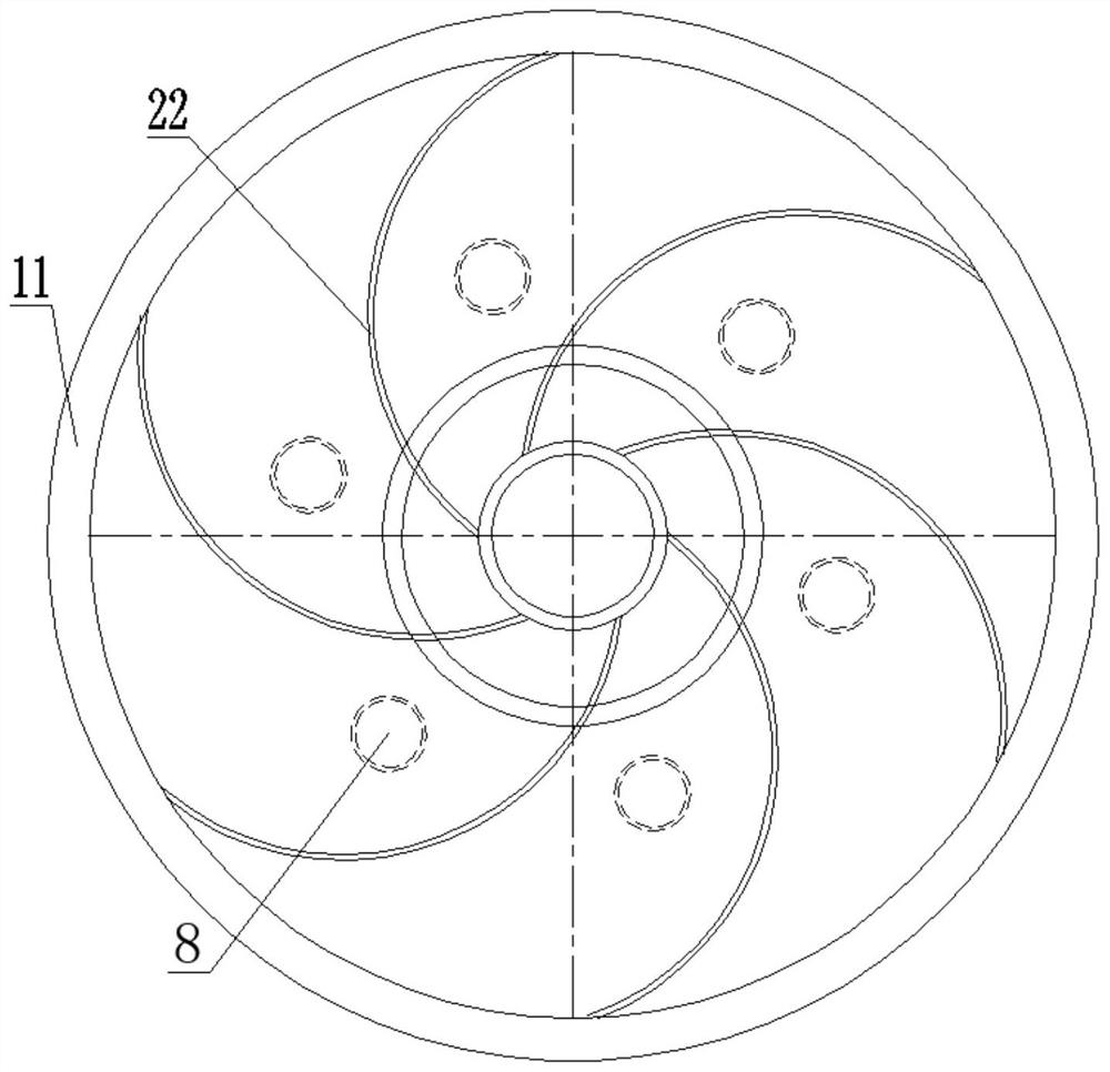
[0032] see Figure 1-3 , a large outer diameter narrow flow channel impeller mold, including a snap-fit ​​upper mold 26 and a lower mold 1 and a core 9 fixedly installed between the upper mold 26 and the lower mold 1, the lower mold 1 is provided with The connected lower hub cavity 5 and the lower cover plate cavity 6, the bottom of the lower mold 1 is equipped with an auxiliary block 2, and the bottom of the lower hub cavity 5 communicates with the sprue 3 pr...


PUM


Abstract

According to the large-outer-diameter narrow-runner impeller mold and the impeller manufacturing method, air holes in a molding sand mold are directly printed through 3D printing, so that the air holes in the sand mold are reasonably distributed, the air permeability is good, deformation of the sand mold during casting is remarkably reduced, the matching size of all parts of the sand mold is accurate, the casting precision is high, the product stability is good, and the production period is short; yield is high, and cost is low; an upper positioning boss and a lower positioning boss are symmetrically designed in the upper die and the lower die respectively and are used for supporting and positioning an impeller mold core, so that the problems that the impeller with the large outer diameter and the narrow flow channel is easy to deform and large in deviation are solved; after the casting is cast out, the holes formed in the upper cover plate and the lower cover plate by the upper positioning boss and the lower positioning boss are filled and welded by adopting the hole filling blocks made of the same metal material as the impeller, the holes are of circular structures, the stress is small after casting, filling and welding, and the strength of the impeller is guaranteed.

Description

technical field [0001] The invention relates to the technical field of centrifugal pump impeller manufacturing, in particular to a mold for a large outer diameter narrow channel impeller and a method for manufacturing the impeller. Background technique [0002] The circulating pump used in the adsorption separation process of the petrochemical PX unit usually requires a centrifugal pump with high head and low cavitation performance. In order to meet the requirements of high head and low cavitation performance of the impeller, such as Figure 4 The shown impeller structure includes blades 22, hub 24, upper cover plate 20, lower cover plate 21, and flow channel 23 formed by upper cover plate 20, lower cover plate 21 and blades 22. This type of impeller is usually designed with a large outer diameter 1. The narrow channel structure is the impeller with large outer diameter and narrow channel. Due to the narrow channel and large diameter of this type of impeller, the core is easy...

Claims


Application Information

Patent Timeline
IPC IPC(8): B22C9/02B22C9/08B22C9/10B22C9/22B22D31/00B33Y10/00B33Y50/02B33Y80/00
CPCB22C9/02B22C9/22B33Y10/00B33Y50/02B33Y80/00B22C9/082B22C9/088B22C9/108B22D31/005
Inventor 杨春野杨顺银高振中林疆哈蔡星星李林锋陈善敏谢功耋陈永良
Owner EBARA GREAT PUMPS
Learn More