Full-automatic assembling and welding equipment for pressure controller
A technology of welding equipment and controller, which is applied in the field of fully automatic assembly welding equipment for pressure controllers, can solve the problems that the trigger tube is prone to inclination, affects product quality, and it is difficult to ensure the verticality of the trigger tube and pressure plate welding, so as to improve the product quality. The effect of processing quality, improving welding quality and ensuring stability
- Summary
- Abstract
- Description
- Claims
- Application Information
AI Technical Summary
Problems solved by technology
Method used
Image

Examples
Embodiment 1
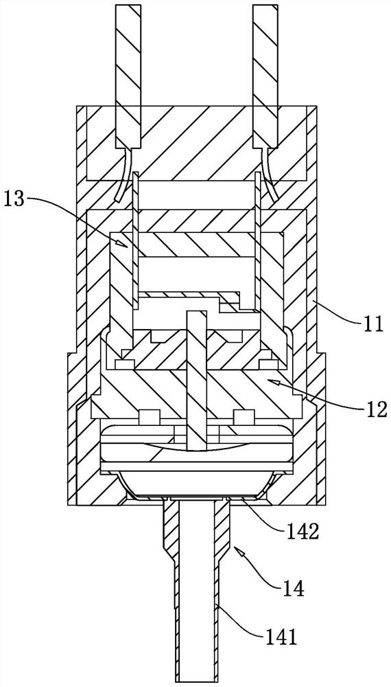
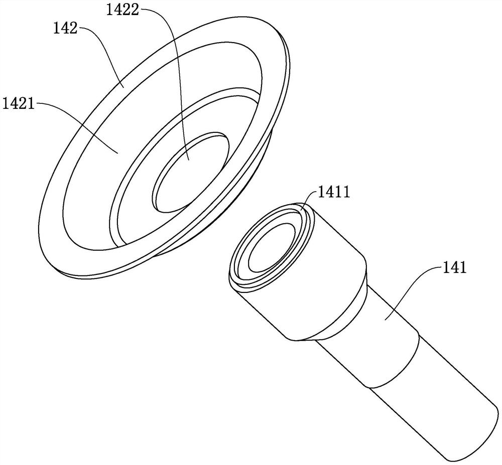
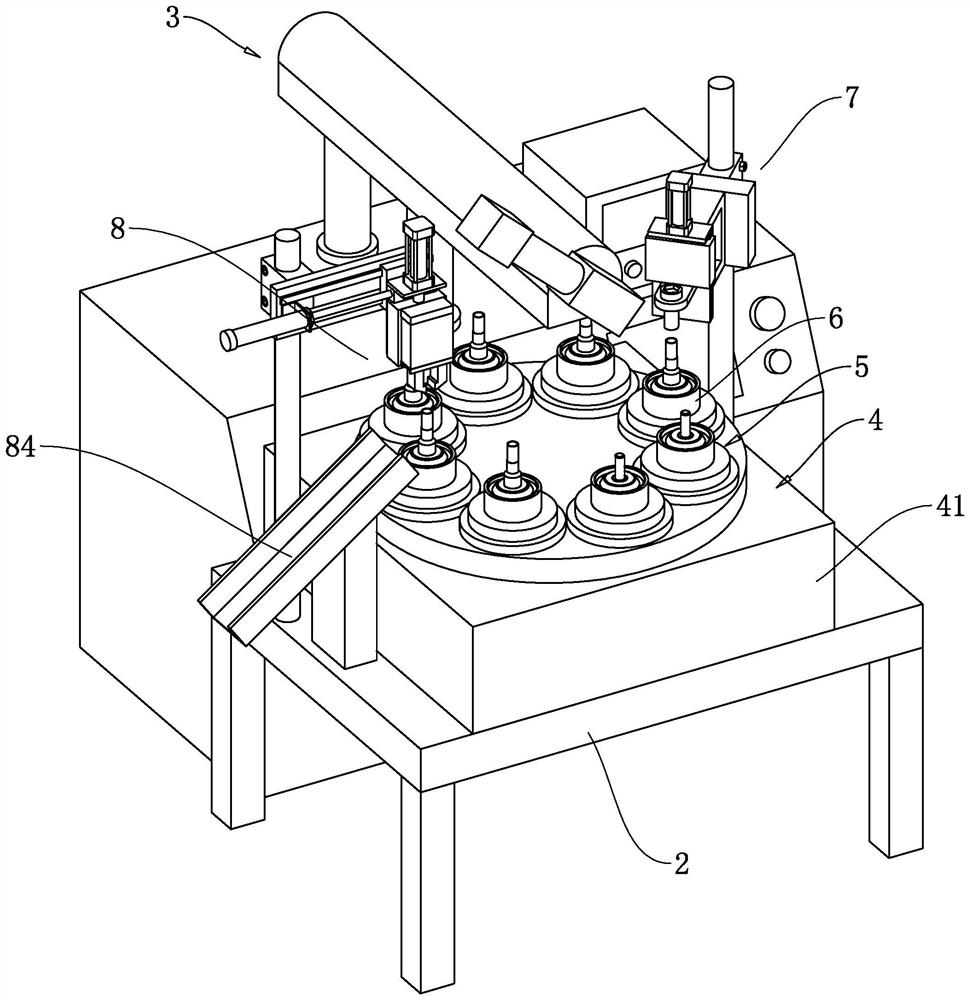
[0048] The embodiment of the present application discloses a fully automatic assembly and welding equipment for a pressure controller. refer to figure 2 and image 3 , a fully automatic assembly and welding equipment for pressure controllers includes a workbench 2, a rotating transposition seat 4, a number of rotating seats 5, a laser welding device 3 and an automatic feeding mechanism 8. The rotary transposition seat 4 is fixed on the workbench 2, and several rotary transposition seats 5 are installed on the rotary transposition seat 4 and arranged evenly along the circumference of the rotary transposition seat 4, and the rotary transposition seat 4 is used to drive the rotary transposition seat 5 Rotate around the central axis of the rotary transposition seat 4, each rotary transposition seat 4 is fixed with a mold base 6 for installing a pressure plate 142 and a trigger tube 141, and the rotary transposition seat 4 is used to drive the mold base 6 to rotate. The laser we...
Embodiment 2
[0063] refer to Figure 10 and Figure 11 The difference between the embodiment of the present application and embodiment 1 is that the clamping assembly 83 includes a cannula 833 and an inflation bag 834, the side wall of the installation block 822 is welded and fixed with a support plate 835 horizontally, and the cannula 833 is vertically penetrated on the support plate 835, and the intubation tube 833 is fixedly connected with the support plate 835, the inside of the intubation tube 833 is formed with an expansion cavity 8331, the expansion air bag 834 is located in the expansion cavity 8331, and the expansion air bag 834 is bonded and fixed in the expansion cavity 8331, and the expansion air bag 834 Connect to the air supply system through the air tube. The outer wall of the intubation tube 833 is provided with a plurality of expansion ports 8332, the expansion ports 8332 are evenly arranged along the circumference of the intubation tube 833, the expansion ports 8332 comm...
Embodiment 3
[0066] refer to Figure 12 and Figure 13 The difference between the embodiment of the present application and embodiment 1 is that: the bottom surface of the first connecting plate 723 is welded and fixedly connected with a pressure rod 91, and the end of the pressure rod 91 far away from the first connecting plate 723 is welded and fixed with a pressure ring plate 92. The ring plate 92 is coaxial with the mold base 6, and the inner diameter of the pressing ring plate 92 is the same as the outer diameter of the mold base 6. Several space-limiting structures 9 are installed in the mold base 6, and the space-limiting mechanism includes an insert block 93, a push rod 94 and a return spring 95. In this embodiment, four space-limiting structures 9 are provided, and the four space-limiting structures 9 are arranged along the mold The circumferential direction of seat 6 is evenly arranged.
[0067] refer to Figure 13 and Figure 14 , the circumferential inner wall of the mold c...
PUM
 Abstract
Description
Claims
Application Information
 - R&D
- Intellectual Property
- Life Sciences
- Materials
- Tech Scout
- Unparalleled Data Quality
- Higher Quality Content
- 60% Fewer Hallucinations
Browse by: Latest US Patents, China's latest patents, Technical Efficacy Thesaurus, Application Domain, Technology Topic, Popular Technical Reports.
© 2025 PatSnap. All rights reserved.Legal|Privacy policy|Modern Slavery Act Transparency Statement|Sitemap|About US| Contact US: help@patsnap.com