Dissimilar metal joint and electric resistance welding method thereof

A dissimilar metal, resistance welding technology, applied in the direction of resistance welding equipment, resistance electrode holder, metal processing equipment, etc., can solve the problems of easy initiation of cracks, low welding strength, large brittle intermetallic compounds, etc., and achieve high-quality connection, method Convenience and the effect of improving welding quality

Active Publication Date: 2022-03-22
SHANGHAI INST OF OPTICS & FINE MECHANICS CHINESE ACAD OF SCI
View PDF5 Cites 3 Cited by
  • Summary
  • Abstract
  • Description
  • Claims
  • Application Information

AI Technical Summary

Problems solved by technology

[0005] The object of the present invention is to provide a resistance welding method for joints of dissimilar metals to solve the problem of low welding strength and a large amount of brittle metal at the welding interface during resistance spot welding of dissimilar metals Intercompounds, easy to initiate cracks

Method used


Image

  • Dissimilar metal joint and electric resistance welding method thereof
  • Dissimilar metal joint and electric resistance welding method thereof
  • Dissimilar metal joint and electric resistance welding method thereof

Examples


Embodiment 1

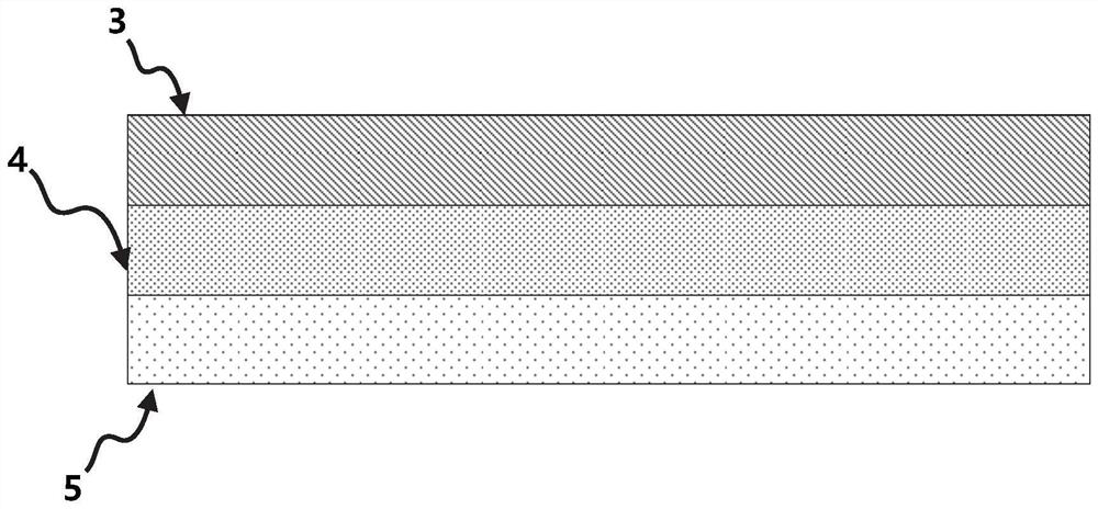
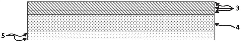
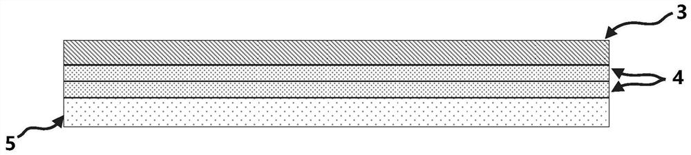
[0095] Select CR210 cold-rolled steel with a thickness of 0.8mm and a tensile strength lower than 400MPa as the upper plate 3, AA 6016 aluminum alloy with a thickness of 0.8mm as the inner plate 4, and CR420 cold-rolled steel with a thickness of 1.0mm and a tensile strength lower than 600MPa. Rolled steel is used as the lower plate 5, the first welding electrode 1 and the second welding electrode 2 are ordinary spherical electrodes, and the welding end surface of the electrodes is 6mm; the specific welding process parameters are shown in Table 1, and the peeling fracture after welding is as follows Figure 9 As shown, on the interface between the inner plate 4 and the lower plate 5, there are solidified light metal splashes 7 distributed radially around the solder joints; the tensile shear load test results of the welded joints are shown in Table 2, because A solid steel-to-steel welding nugget is formed between the first type of metal plates 3, 5 and the second metal plate 4, ...

Embodiment 2

[0097] The CR210 cold-rolled steel with a thickness of 1.0 mm and a tensile strength lower than 400 MPa is selected as the upper plate 3, and the AA 5754 aluminum alloy with a thickness of 1.2 mm is used as the inner plate 4. The difference in material selection from Example 1 is that the inner plate 4 is 5 Aluminum alloy; CR420 cold-rolled steel with a thickness of 1.0mm and a tensile strength lower than 600MPa is used as the lower plate 5, and the first welding electrode 1 and the second welding electrode 2 are ordinary spherical electrodes, and the welding end surface of the electrode is 6mm. The welding process parameters are shown in Table 1, and the cross-sectional metallographic diagram of the joint is shown in Figure 10 shown. After welding, the tensile shear load test is carried out on the joint, and the tensile shear load-displacement curve is as follows Figure 11 shown. The tensile shear load test shows that the joint has a very high tensile shear strength of 72...

Embodiment 3

[0099] Select Q&P980 cold-rolled high-strength steel with a thickness of 1.0mm as the upper plate 3, and its tensile strength is generally not less than 1000MPa; AA 5754 aluminum alloy with a thickness of 1.5mm is used as the inner plate 4, and Q&P1180 cold-rolled high-strength steel As the lower plate 5, its tensile strength is generally not less than 1200MPa; the first welding electrode 1 and the second welding electrode 2 are both ordinary spherical electrodes, and the welding end surface of the electrodes is 6mm. The specific welding process parameters are shown in Table 1. After welding, the tensile shear load test was carried out on the joint. The test showed that the joint also had a very high tensile shear strength, reaching 7557.6N. The peak load test results of tensile shear are shown in Table 2.


PUM

PropertyMeasurementUnit
Densityaaaaaaaaaa
Melting pointaaaaaaaaaa
Thicknessaaaaaaaaaa

Abstract

The invention provides an electric resistance welding method for a dissimilar metal joint. The electric resistance welding method is used for welding a laminated structure, wherein an outer layer is made of iron or an iron-based alloy, and an inner layer is made of metal with the density smaller than 5g / cm < 3 > or the melting point lower than 800 DEG C. The electric resistance welding method comprises a splashing stage, and in the splashing stage, light metal or low-melting-point metal in the middle of the stacked structure is separated in a splashing mode, so that iron or iron-based alloy layers in a welding interface directly form a connecting structure to complete welding. According to the method, the formation of brittle intermetallic compounds on the welding interface of the dissimilar joint can be avoided, the mechanical property of the joint is improved, and reliable connection between dissimilar metals is realized. The invention further provides a dissimilar metal joint.

Description

technical field [0001] The invention belongs to the field of welding, and in particular relates to a dissimilar metal joint and a resistance welding method thereof. Background technique [0002] With the continuous improvement of energy saving and emission reduction requirements, lightweight design has become an important issue facing the automotive industry. Among the products of a few luxury brands, design schemes such as all-aluminum body have appeared. However, the all-aluminum body is expensive and difficult to maintain, and its price has always been difficult to be widely accepted by ordinary consumers. Therefore, in the mainstream products on the market, the main body of the body structure is still dominated by steel, especially structural parts such as A-pillars, B-pillars, door reinforcement panels and longitudinal beams. High-strength steel and even ultra-high-strength steel are replacing the original ordinary Steel is gaining more and more applications. At the ...

Claims


Application Information

Patent Timeline
IPC IPC(8): B23K11/31B23K11/36
CPCB23K11/31B23K11/36
Inventor 李铭锋杨上陆陶武王艳俊
Owner SHANGHAI INST OF OPTICS & FINE MECHANICS CHINESE ACAD OF SCI
Why Eureka
Try Eureka