Formed grinding wheel gear grinding machine tool

A technology for forming grinding wheels and grinding teeth, which is applied to gear teeth, parts of grinding machine tools, mechanical equipment, etc., can solve the problems of affecting processing efficiency, low processing accuracy, and high proportion of auxiliary time, so as to improve meshing stability and improve The effect of processing efficiency and good process guarantee

Active Publication Date: 2022-03-25
HUNAN ZDCY (ZHONGDA CHUANG YUAN) CNC EQUIP CO LTD
View PDF6 Cites 3 Cited by
  • Summary
  • Abstract
  • Description
  • Claims
  • Application Information

AI Technical Summary

Problems solved by technology

[0008] First, in the process of grinding wheel dressing and tooth surface grinding, the Y-axis moves to cooperate with the workpiece with large actual tooth thickness grinding allowance and radial grinding allowance, and completes the cutting required for each tooth groove grinding The movement of the moving Z-axis is relatively large, and the wear of the corresponding supporting guide rail and the driven ball screw is correspondingly large, and the large amount of wear leads to a decrease in the accuracy of the Z-axis
On the one hand, when the Z-axis of the grinding tool is used for dressing the grinding wheel, it directly affects the dressing accuracy of the grinding wheel; on the other hand, the dressing accuracy of the grinding wheel in the early stage is acceptable. The shape accuracy of the tooth profile is getting worse and worse, the machining accuracy is low, and the machining accuracy is unstable
[0009] Second, when dressing the grinding wheel, it is necessary to move the X-axis away from the processing area, then turn the A-axis, move the Z-axis to move the grinding wheel from the grinding position to the dressing position, and then dress the grinding wheel; after the grinding wheel is dressed, return to the grinding area It is necessary to turn the A-axis until the axis of the grinding wheel intersects with the axis of the workpiece gear to form a helical angle, and then move the X-axis and Z-axis to the grinding position. The conversion process from grinding gear to dressing wheel and from dressing wheel to grinding gear is time-consuming. many
The grinding wheel dressing needs to be performed many times in the whole grinding process, and each dressing process needs to consume two conversion processes from the grinding area to the dressing area and from the dressing area to the grinding area, resulting in auxiliary Too much time
In addition, the grinding wheel dressing needs to rotate the A-axis first. Based on the characteristics of the large moment of inertia of the A-axis, the rotation speed of the A-axis is generally set to be very low (5rpm-10rpm), which directly affects the processing efficiency and the grinding efficiency of the entire workpiece gear. cannot be effectively controlled

Method used


Image

  • Formed grinding wheel gear grinding machine tool
  • Formed grinding wheel gear grinding machine tool
  • Formed grinding wheel gear grinding machine tool

Examples


Embodiment Construction

[0038] In order to enable those skilled in the art to better understand the technical solutions of the present invention, the present invention will be further described in detail below in conjunction with the accompanying drawings and specific embodiments.

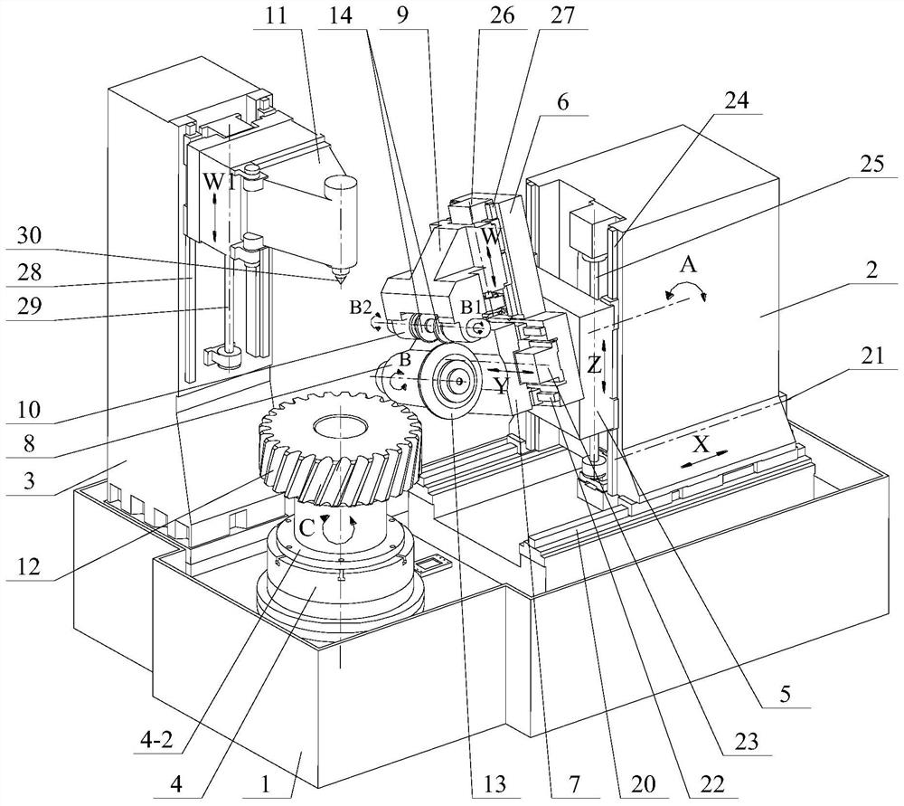
[0039] See figure 1 , which is a schematic diagram of a use state of the profile grinding wheel gear grinding machine tool described in this embodiment.

[0040] The form grinding wheel gear grinding machine tool includes five linear axes of X, Y, Z, W and W1 and seven rotary axes of A, B, B1, B2 and C under the use state of grinding external teeth. Here, "linear axis" refers to the motion displacement relationship between the matching components in the corresponding linear direction, and "rotational axis" means the motion displacement relationship between the matching components in the corresponding rotation direction. It should be understood that the above-mentioned dimension limitations are used to clearly describe t...


PUM


Abstract

A Z-axis sliding table of the gear grinding machine tool is arranged on a stand column and can move along the Z axis relative to the stand column, an A-axis rotary table of the gear grinding machine tool is arranged on the Z-axis sliding table and can rotate around the A axis relative to the Z-axis sliding table, and a Y-axis sliding table of the gear grinding machine tool is arranged on the A-axis rotary table and can move along the Y axis relative to the A-axis rotary table. A W-axis sliding table is arranged on an A-axis rotary table and can move along a W axis relative to the A-axis rotary table; the grinding wheel spindle box is arranged on the Y-axis sliding table, and an outer tooth grinding wheel is detachably arranged on the grinding wheel spindle box. An outer tooth dressing spindle box is arranged on the W-axis sliding table, and an outer tooth dressing grinding wheel is arranged at the power output end of the outer tooth dressing spindle box; the Z axis is the grinding feeding direction, the X axis is the grinding feeding and retracting direction, the Y axis is the displacement direction of the grinding wheel spindle box along the axis of the grinding wheel spindle box, and the W axis is the direction in which the external tooth dressing grinding wheel is close to or far away from the external tooth grinding wheel in the radial direction of the external tooth grinding wheel. By applying the scheme, the machining precision and the grinding efficiency can be effectively improved.

Description

technical field [0001] The invention relates to the technical field of mechanical processing, in particular to a gear grinding machine tool for forming grinding wheels. Background technique [0002] With the rapid development of the economy and the advancement of technology, people's living standards are getting higher and higher, and higher requirements are put forward for the basic necessities of life, food, housing, transportation and the surrounding environment. Various standards have stricter restrictions on noise. As we all know, the precision of gear machining directly affects the working noise generated during its use, such as but not limited to, gear transmission mechanisms used in marine engineering, ships, locomotives, wind power, military and other industries. [0003] In the prior art, gear grinding technology is used to improve the machining accuracy of gears, mainly including two methods of generating grinding and forming grinding. The traditional generating ...

Claims


Application Information

Patent Timeline
Patent Type & Authority Applications(China)
IPC IPC(8): B23F1/02B23Q1/25B24B53/06B24B53/075B24B53/14
CPCB23F1/02B23Q1/25B24B53/062B24B53/075B24B53/14Y02P70/10
Inventor 李建军李欢钟洪海
Owner HUNAN ZDCY (ZHONGDA CHUANG YUAN) CNC EQUIP CO LTD
Why Eureka
Try Eureka