Automatic double-speed control motor after secondary electrification

A control relay, two-speed technology, applied in the direction of DC motor rotation control, excitation or armature current control, connection with control/drive circuit, etc. , to achieve the effect of improving material utilization and work efficiency, improving work mode and simple operation

Pending Publication Date: 2022-03-25
杭州广力机电科技有限公司
0 Cites 0 Cited by

AI-Extracted Technical Summary

Problems solved by technology

[0003] DC series motors are generally used on automobile electric winches. This kind of DC series motor has large starting torque and high no-load speed. However, when commutating this type of motor, it is generally necessary to use Only four pairs of contactors with large area contacts can achieve reversing, the reversing efficiency is low, the loss is large, and the cost is high. Moreover, it is very difficult to adjust the speed of this type of high-current series-excited motor, and the magnetic field coil current of the parallel-excited DC motor is small. Only a pair of large-area contactors are needed to control the main circuit. The commutation control current is small, and it is relatively easy to achieve commutation and change the magnetic field to change the speed. However, the starting torque of this type of motor...

Method used

In the control box (5) as shown in accompanying drawing 2, stretch out the various bosses of length on different positions, reverse contactor copper bar (51), Siamese copper bar (52), forward contactor Copper bar (53), overtravel spring (59), moving contact (60), breaking spring (61), diode (62), pull-in coil (63), holding coil (64) and iron core, coil keel and The iron bars form a conjoined reverse contactor and a forward contactor, which jointly take power from the conjoined copper bar (52), and one end of the pull-in coil (63) is connected to its corresponding reverse contactor through an isolated diode (62). On the copper strip of the contactor (51) or the copper strip of the forward contactor (53), after the contactor is energized, the pull-in coil (63) is short-circuited to make it de-energized, so that no power consumption is generated and no heat is generated. At this time, only the coil is kept (64) Power on, low power consumption and ensure the normal operation of the contactor, the reverse contactor copper strip (51), the forward contactor copper strip (53), the connected copper strip (52) and the moving contact (60) are fully Use the protrusions protruding from the control box (5) to position, press and limit, to...

Abstract

An automatic double-speed control motor after secondary electrification comprises a motor excitation soft coil (1), a motor excitation hard coil (2), an electric brush (3), a motor rotor (4), a control box (5), a reverse direction contactor, a forward direction contactor, a direction relay (54), a secondary reverse rotation controller (55), a control relay (56) and the like, the automatic double-speed control motor after secondary electrification is applied to an automobile electric winch and an electric fork truck hydraulic unit, a motor excitation hard coil (2), an electric brush (3) and a motor rotor (4) are connected in series, a motor excitation soft coil (1) is connected in parallel in the forward direction, the motor rotates in the forward direction, after secondary electrification operation is carried out within limited time, the motor excitation soft coil (1) does not participate in working, and the motor excitation soft coil (1) does not participate in working. And the electric brush (3) and the motor rotor (4) are conducted, the motor excitation hard coil (2) is reversely conducted, then the motor excitation hard coil (2) is reversely connected to the motor excitation soft coil (1) for parallel operation, and the motor rotates reversely.

Application Domain

Technology Topic

Image

  • Automatic double-speed control motor after secondary electrification
  • Automatic double-speed control motor after secondary electrification

Examples

  • Experimental program(1)

Example Embodiment

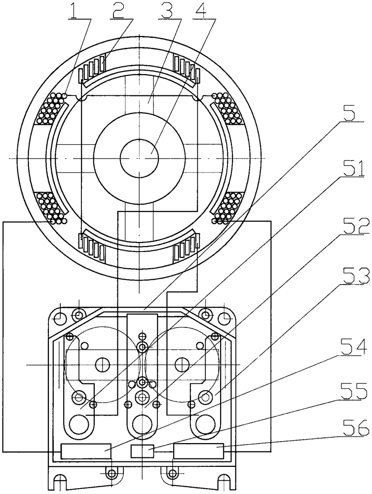
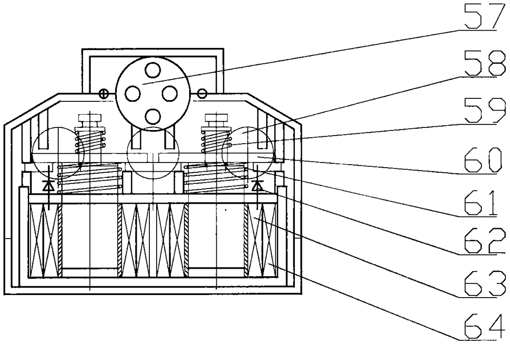
[0012] The automatic two-speed control motor after the secondary power-on of the present invention is as follows: figure 1 and figure 2 As shown, it includes: motor excitation soft coil (1), motor excitation hard coil (2), brush (3), motor rotor (4), control box (5), reverse contactor copper strip (51), Conjoined copper strip (52), positive contactor copper strip (53), directional relay (54), secondary reverse controller (55), control relay (56), control connector (57), waterproof pull-out Take off (58), overtravel spring (59), moving contact (60), breaking spring (61), diode (62), pull-in coil (63), holding coil (64) and coil keel, iron bars and iron core. The automatic two-speed control motor after the second power-on is applied to the hydraulic unit of the car electric winch and the electric stacker. The motor excitation soft coil (1) is composed of multiple enameled thin wires and arranged symmetrically on the left and right, because the enameled thin wires Small area, large number of strands, large resistance, and small current when working in parallel. Industrialized batch-manufactured directional relays (54), secondary inversion controllers (55) and control relays (56) can be used to achieve control. The directional relay (54), the secondary reversing controller (55), and the control relay (56) are installed in the space below the cable at the exit (58), which fully utilizes each space in the control box (5) and reduces the Volume, reduce cost, and facilitate the installation and use of the product, the motor excitation hard coil (2) is composed of a small number of thick copper wires and is arranged symmetrically up and down, the control box (5), the control connector (57), the direction relay (54) , the secondary reverse controller (55), the control relay (56) and the forward contactor copper strip (53) conduct the motor excitation hard coil (2), the brush (3) and the motor rotor (4) in series and connect the motor The excitation soft coil (1) is connected in parallel in the forward direction. At this time, the magnetic field of the motor is jointly generated by the excitation hard coil (2) and the motor excitation soft coil (1). Or lifting action, after the secondary power-on operation within a limited time, no additional switch is required, and the secondary inversion controller (55) applies the characteristics of the capacitor charging and discharging that takes time and the difference between the starting voltage and the release voltage of the control relay (56). , automatically reverse the first function of the secondary reverse control relay (56), there are two reverse function modes: one mode is that if the first control relay (56) is turned on, the second time is not The other mode is that if the control relay (56) is not conducting for the first time, it is conducting for the second time. Under this control, the motor excitation soft coil (1) does not participate in the work, and the forward contactor The copper strip (53) only conducts the motor excitation hard coil (2), the brush (3) and the motor rotor (4) in series, the magnetomotive force is small, realizes the forward fast rotation, controls the connector (57), reverse contact The copper strip (51), the directional relay (54) and the control relay (56) conduct the brush (3) and the motor rotor (4), and reversely conduct the motor excitation hard coil (2) and then reversely connect to the motor The excitation soft coil (1) works in parallel, and the motor rotates in the reverse direction to achieve fast light-load speed and heavy-load torque and reverse rotation. The reverse working current of the motor is small, and the wire diameter of the reverse wire can be small. Corresponding control wires can be accommodated in the wire and cable, and are connected to the motor after being outputted from the same waterproof pull-out (58).
[0013] as attached figure 2 In the control box (5) shown, various bosses of different lengths protrude from different positions, the reverse contactor copper strip (51), the conjoined copper strip (52), the forward contactor copper strip (53), the super The process spring (59), the moving contact (60), the breaking spring (61), the diode (62), the pull-in coil (63), the holding coil (64) and the iron core, the coil keel and the iron bar form a conjoined counter. The forward contactor and the forward contactor take power together on the conjoined copper bar (52), and one end of the pull-in coil (63) is connected to its corresponding reverse contactor copper bar (51) through the isolated diode (62) Or on the copper strip (53) of the positive contactor, after the contactor is energized, short-circuit the pull-in coil (63) to make it disconnected from the energization, no power consumption is generated, and no heat is generated. At this time, only the coil (64) is kept energized, and the power consumption is To ensure the normal operation of the contactor, the reverse contactor copper strip (51), the forward contactor copper strip (53), the conjoined copper strip (52) and the moving contact (60) are fully used in the control box (5) The protruding bosses are positioned, pressed and limited to ensure that the moving contacts (60) are spaced apart and dissipated. Waterproof outgoing cables, because the normally open or normally closed circuit controlled by the conjoined contactor and the control box (5) are made of engineering plastics, and the overtravel spring (59), the moving contact (60) and the breaking spring (61) are in direct contact with each other. , The coil keel is made of reinforced nylon material, which has self-lubricating properties, and the frequency of use of the automotive electric winch and the hydraulic unit of the electric stacker is not high. The iron core is in direct contact with the coil keel and the bottom iron bar. Each wire is integrally connected on a circuit board and fixed in the box, the structure is simplified, and the manufacturability is good.
[0014] The automatic two-speed control motor after secondary power-on of the present invention fully and specifically analyzes the working characteristics of the forward and reverse rotation of the motor, and develops a conjoined contactor and its control system in a targeted manner, which is small in size, low in cost and good in performance. Strong practicality.

PUM

no PUM

Description & Claims & Application Information

We can also present the details of the Description, Claims and Application information to help users get a comprehensive understanding of the technical details of the patent, such as background art, summary of invention, brief description of drawings, description of embodiments, and other original content. On the other hand, users can also determine the specific scope of protection of the technology through the list of claims; as well as understand the changes in the life cycle of the technology with the presentation of the patent timeline. Login to view more.

Similar technology patents

Multiple extruder configuration

InactiveUS7017732B2High mean residence timeHigh torqueRotary stirring mixersMixing/kneading with horizontally-mounted toolsBiomedical engineeringTwin screw extruder
Owner:BERSTORFF GMBH

Optimization of gimbal control loops using dynamically measured friction

InactiveUS20160139584A1High torqueDefence devicesComputer controlPeak currentSoftware
Owner:BAE SYST INFORMATION & ELECTRONICS SYST INTERGRATION INC

Classification and recommendation of technical efficacy words

  • High torque
  • Easy to operate
Why Eureka
Try Eureka