Mixing device for combustion production of new energy biomass particles

A technology of biomass particles and mixing devices, which is applied in the direction of biofuels, mixers, waste fuels, etc., to achieve the effects of easy removal, improved work efficiency, and convenient operation

Pending Publication Date: 2022-03-29
蔡煜
View PDF5 Cites 0 Cited by
  • Summary
  • Abstract
  • Description
  • Claims
  • Application Information

AI Technical Summary

Problems solved by technology

[0005] In order to overcome the disadvantage that it takes extra time to transfer raw materials from other cutting equipment when people use most of the existing mixing devices to produce biomass new energy, the present invention provides a new energy with automatic shredding function Mixing device for biomass pellet combustion production

Method used


Image

  • Mixing device for combustion production of new energy biomass particles
  • Mixing device for combustion production of new energy biomass particles
  • Mixing device for combustion production of new energy biomass particles

Examples


Embodiment 1

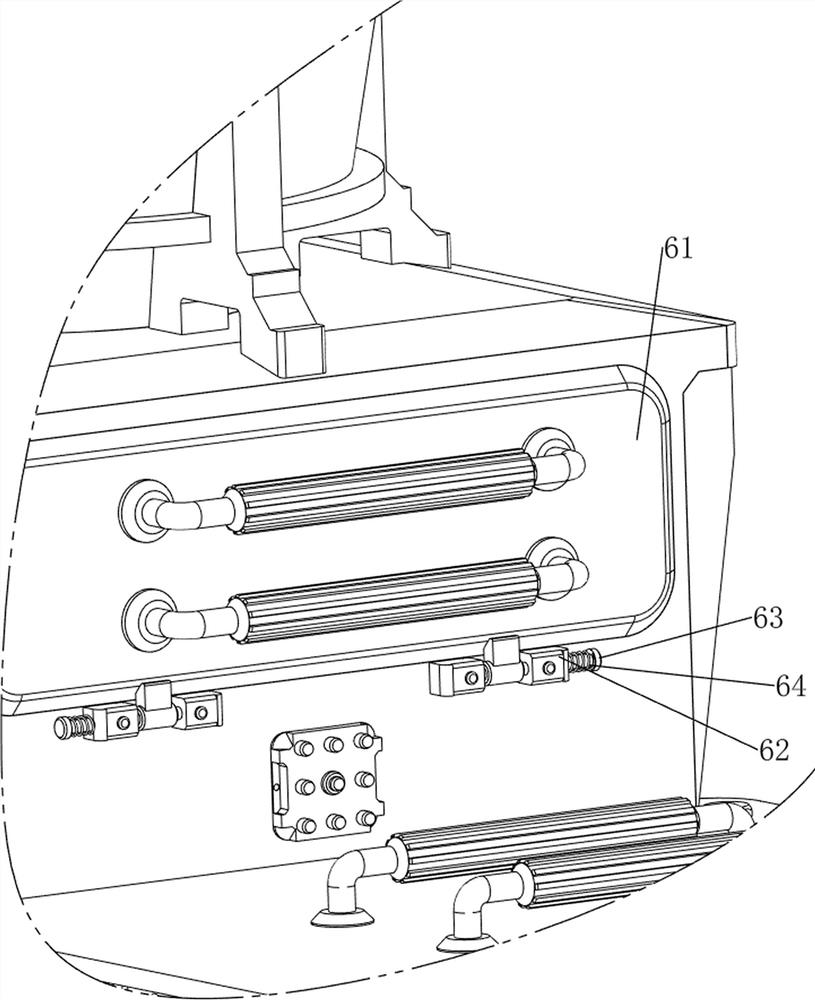
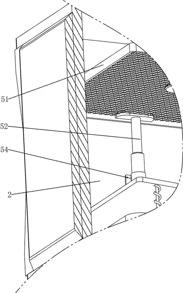
[0042] A mixing device for new energy biomass particle combustion production, including a bottom plate 1, a first working box 2, a control box 3, a first rotating shaft 31, a first fixing part 32, a cutting part 33, a mixing mechanism 4, and a toggle mechanism 5. Collecting mechanism 6 and discharging mechanism 7, see Figure 1-Figure 13 As shown, the first working box 2 is welded on the left side of the top of the bottom plate 1, and a rubber pad is connected to the four corners of the bottom of the bottom plate, the rubber pad increases the friction with the ground to prevent slipping, and the upper right side of the first working box 2 is provided with The control box 3 is provided with a first fixing part 32 in the middle of the upper part of the first working box 2, and a first rotating shaft 31 is arranged in the middle of the bottom of the first fixing part 32, and a cutting part 33 is arranged on the upper side of the first rotating shaft 31. The cutting part 33 When r...

Embodiment 2

[0049] On the basis of Embodiment 1, a dust-proof mechanism 8 is also included. The dust-proof mechanism 8 includes a blanking frame 81, a second cover plate 82, a third rotating shaft 83 and a second torsion spring 84. See figure 1 , figure 2 , image 3 , Figure 14 and Figure 15 As shown, the top of the first working box 2 is welded with a blanking frame 81, and the left side of the blanking frame 81 top is rotatably provided with a third rotating shaft 83, and the third rotating shaft 83 is provided with a second cover plate 82, and the second cover plate 82 After turning and closing, it can prevent the raw materials from flying outwards when being chopped. The second cover plate 82 blocks the top of the blanking frame 81, and a second torsion spring 84 is provided between the front side of the third rotating shaft 83 and the blanking frame 81.

[0050] When people need to load raw materials, the second cover plate 82 can be rotated to open, the second cover plate 82 d...


PUM


Abstract

The invention relates to a mixing device, in particular to a mixing device for combustion production of new energy biomass particles. The invention aims to provide a mixing device for combustion production of new energy biomass particles with an automatic chopping function. The mixing device for new energy biomass particle combustion production comprises a bottom plate, a first working box, a control box, a first fixing part and the like, the first working box is arranged on the left side of the top of the bottom plate, the control box is arranged on the upper portion of the right side of the first working box, and the first fixing part is arranged in the middle of the upper portion of the first working box. Raw materials are placed on the top of the first working box, a driving motor starts to work, a cutting part and a stirring part can rotate, then the raw materials are pushed to move to the cutting part, the cutting part can automatically cut the raw materials, the stirring part can automatically stir the cut raw materials, and therefore operation of people is facilitated; and the working efficiency of people is improved.

Description

technical field [0001] The invention relates to a mixing device, in particular to a mixing device for new energy biomass particle combustion production. Background technique [0002] New energy biomass is a new renewable and environmentally friendly energy material that can replace traditional petroleum and diesel oil. It is an important direction for future energy development. The stalks of crops are crushed, and processed into granular combustibles with low moisture content through mixing and compression processes. In the production process of new biomass energy, peanut shells, corn cobs, branches and leaves, The mixing process after crushing hay, crop straw, etc. is an indispensable and extremely important step. Due to the problem of uneven stirring and slow stirring speed in the use of the existing mixing device, it is not conducive to large-scale rapid production . [0003] Patent application CN213222020U, with a publication date of 20210518, discloses a mixing device...

Claims


Application Information

Patent Timeline
Patent Type & Authority Applications(China)
IPC IPC(8): B01F23/70B01F27/90B01F33/83B01F35/21B01F35/75C10L5/44
CPCC10L5/442C10L5/445Y02E50/30Y02E50/10
Inventor 蔡煜
Owner 蔡煜
Why Eureka
Try Eureka