Multi-mode switching wide output direct current converter and switching control thereof

A DC converter, multi-mode technology, applied in the direction of output power conversion device, DC power input conversion to DC power output, control/regulation system, etc., can solve the problem of reactive power circulation reducing converter efficiency and long-term use of unsuitable equipment Life, unable to meet application requirements and other issues, to achieve the effect of reducing ripple, reducing current stress, and simple and feasible circuit structure

Pending Publication Date: 2022-03-29
HUNAN UNIV
View PDF0 Cites 1 Cited by
  • Summary
  • Abstract
  • Description
  • Claims
  • Application Information

AI Technical Summary

Problems solved by technology

[0003] The LLC resonant converter has the characteristics of zero-voltage turn-on of the main power tube and high power density, and has been widely used in high-efficiency power converters. However, when the traditional LLC resonant converter is applied to a wide range of ) or pulse width modulation (PWM) control methods face the frequency range is too wide, and ZVS is difficult to achieve under light load conditions, large reactive power circulation reduces the efficiency of the converter, can not meet the application requirements of a wider operating range
[0004] Moreover, in the traditional voltage-type DC converter, the voltage stress of the switching tube is relatively fixed, and the output voltage control is intuitive, but a short-circuit protection circuit with a fast action time is required, and the input current ripple is large, which is not suitable for submarine cable observation stations and other requirements. Where the equipment has a long service life

Method used


Image

  • Multi-mode switching wide output direct current converter and switching control thereof
  • Multi-mode switching wide output direct current converter and switching control thereof
  • Multi-mode switching wide output direct current converter and switching control thereof

Examples


Embodiment Construction

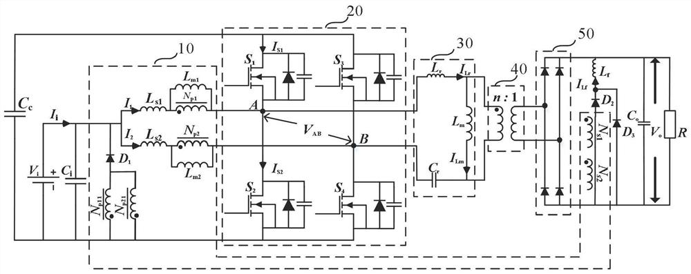
[0039] The wide output DC converter topology proposed by the present invention is as follows figure 1 As shown, it includes 10 coupled inductor circuits, 20 interleaved parallel circuits, 30 resonant cavities, 40 transformers, and 50 rectifiers. I i is the total input current, I 1 , I 2 Leakage inductance L flowing through the coupled inductor, respectively s1 , L s2 current; V AB is the mid-point output voltage of the interleaved parallel circuit; I Lr , I Lm flow through the resonant inductance L respectively r with magnetizing inductance L m current; I S1 , I S2 Respectively, the switching tube S flowing through the first bridge arm 1 , S 2 current.

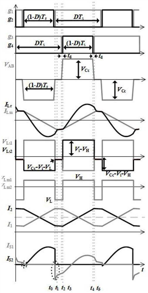
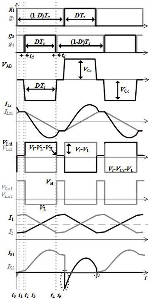
[0040] By changing the modulation method, the wide output DC converter proposed by the present invention can work in three operating modes: HG, MG, and LG respectively: in the HG operating mode, the working process of the proposed wide output DC converter is traditional The working process of the LLC resonant con...


PUM


Abstract

The multi-mode switching wide output direct current converter comprises a coupling inductance circuit, an interleaving parallel circuit, a clamping capacitor, a resonant cavity, a transformer, a rectifier and an output capacitor, and the output voltage is controlled by adjusting the duty ratios of S1, S2, S3 and S4. The multi-mode switching wide output direct current converter can work in three modes, namely a high gain (HG) mode, a medium gain (MG) mode and a low gain (LG) mode. In different modes, the coupling inductance circuit not only plays a role of a filter inductor, but also plays a role of a transformer, so that the power density is improved, meanwhile, the direct-current converter can realize zero-voltage switching of all switching tubes in a wide input working range in an HG mode and an MG mode, the switching loss is effectively reduced, and the conversion efficiency is improved.

Description

technical field [0001] The invention relates to the technical field of switching converters, in particular to a method for realizing wide-range operation of a DC converter in the technical field of power electronics. Background technique [0002] With the rapid development of complex applications such as renewable energy power generation, hybrid electric vehicles, and submarine cable observation stations, the demand for high-efficiency power conversion in a wide range is becoming more and more urgent. Wide voltage gain DC converters have become an integral part of such converters. High efficiency, high power density, wide voltage gain, low cost, and stable and reliable operation are key requirements for such converters. In addition, special requirements such as low current ripple are even key technical indicators for submarine cable observation stations. [0003] The LLC resonant converter has the characteristics of zero-voltage turn-on of the main power tube and high powe...

Claims


Application Information

Patent Timeline
Patent Type & Authority Applications(China)
IPC IPC(8): H02M3/335H02M3/24H02M1/14
CPCH02M3/33569H02M3/24H02M1/14Y02B70/10
Inventor 何志兴刘阳侯仁杰董宏宇罗安管仁锋李宗鉴周芊帆陈燕东周乐明
Owner HUNAN UNIV
Why Eureka
Try Eureka